Mini FAKRA Cable Selection Guide for Multi-Camera Vehicles

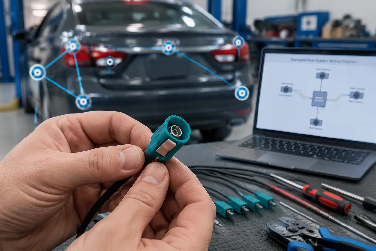
Mini FAKRA is one option among several. Fit depends on the camera module, platform, signal interface, protocol, pinout, and OEM requirements. An automotive camera cable must match them. This connector selection guide starts with interface and signal type, then impedance, data rate, length, coding, shielding, and environment.
TL;DR: A mini fakra cable suits dense multi-camera layouts when the module is designed for that exact interface. Always verify compatibility at the module level rather than by outward appearance.
Key Takeaways
Start with the camera interface and signal type before choosing any connector.
Verify compatibility at the module level, not by appearance alone.
Match impedance and cable length to your specific camera link.
Plan cable routing to respect bend radius and avoid signal damage.
Use a pre-installation checklist to confirm keying, pinout, and latch click.
What Is a Mini FAKRA Cable?
Mini FAKRA, also called HFM (High-Speed FAKRA-Mini), is a next-generation coaxial connector system built for automotive use. It carries high-speed data between camera modules, ECUs, and displays. The term "mini fakra cable" describes the finished assembly, not the connector alone.
Connector vs. Complete Cable Assembly
A Mini FAKRA connector is one part of a larger system. The finished assembly combines three elements: the connector, the coaxial cable, and the termination. Each element affects signal quality. A well-made connector on a poorly terminated cable still fails validation.
You must treat the connector and the assembly as separate purchasing items. The connector defines the mating interface. The cable defines loss, flexibility, and bend radius. The termination defines shielding continuity and mechanical strength. Ask your supplier which part they quote.
Key Electrical and Mechanical Traits
Selected HFM configurations support 50 Ω impedance, frequencies up to 20 GHz, and data rates up to 28 Gbps, depending on the application. Molex reports up to 80% space savings compared with traditional FAKRA connectors. Bafitoprf notes that selected HFM configurations reach 20 GHz and 28 Gbps, while other Mini FAKRA families publish different limits.
Mechanical features matter as much as electrical ones. Keying controls whether two housings can mate at all. A primary latch holds the connector after mating. Connector Position Assurance (CPA) confirms full seating on selected versions. Sealed variants resist water and fluid ingress, but sealing is not standard on every version.
Mini FAKRA is a distinct interface from standard FAKRA. Similar appearance does not prove compatibility. Verify the interface drawing at the module level before you specify any vehicle camera connector.
Why Mini FAKRA Suits Multi-Camera Vehicles
A multi-camera vehicle system adds ports faster than it adds space. Each camera needs its own coaxial path back to the ECU. The smaller format answers that pressure with a compact housing and a modular interface. That density matters most in compact multi-camera systems, where every millimeter counts.
Port Density in Tight Packages
Standard FAKRA builds on the SMB interface with a protective plastic shell. The mini version shrinks that housing for compact vehicle electronic modules. Molex reports up to 80% space savings for its HFM system. TE claims a 75% maximum reduction for its own connector system.
Attribute | Standard FAKRA | Mini FAKRA |
|---|---|---|
Housing size | Larger, SMB-based with plastic shell | Noticeably smaller |
Interface structure | Single coaxial connection | High-density modular interface |
Connection density | One RF connection per housing | Multiple RF ports in one module |
Port count changes the board layout. Premier Cables notes that single, dual, and quad-port options exist in selected systems. One quad housing carries four coaxial ports, so a single interface serves four camera channels. You consolidate connections instead of stacking four separate ports on a crowded board. A shorter connector body also frees room for the camera system cable to exit the module.
Where It Fits and Where It Does Not
Selection starts with the camera interface and signal type. Confirm what the module expects before you compare housings. Then narrow by impedance, data rate, and environmental protection.
This interface fits dense layouts where the module is designed for it. It does not suit every automotive camera system. A platform built around standard FAKRA or HSD keeps its own mating connector. Verify compatibility at the module level, not by appearance. Ask for the interface drawing and the pinout before you commit. Multi-camera systems reward that discipline, and the vehicle camera system gains margin at the harness level. Every automotive camera cable in the bundle competes for the same few millimeters, so the cable choice follows the interface, not the other way around.
Typical Automotive Camera System Applications
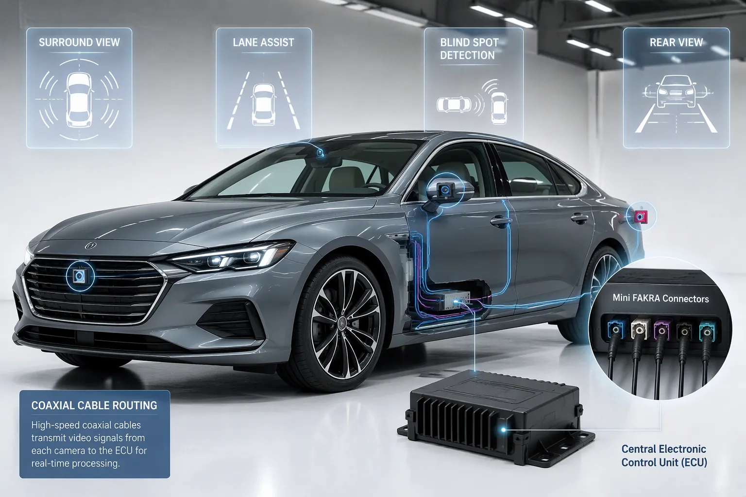
Camera count drives connector choice. A single rear camera needs one path. A surround-view setup needs four or more. Each added camera raises port density and harness complexity. TE lists the applications that commonly use its Mini FAKRA connector system:
Surround View
Lane Assist
Blind Spot Detection
Traffic Sign Recognition
Rear View
Driver Monitoring
Gesture Control
Night Vision
Mirror Replacement
Treat that list as a starting point, not a guarantee. Suitability depends on the application, the module design, and the OEM specification.
Surround-View, Parking, and Rear-View Cameras
A 360-degree surround-view system combines several wide-angle cameras into one stitched image. Each camera feeds its own coaxial run back to the ECU. A surround-view camera cable must hold signal integrity across that run. Parking and rear-view cameras follow the same pattern. They sit at the vehicle edge, so their cables cross tight body cavities and pass through grommets. Short, sealed assemblies often fit best here, depending on the application.
ADAS, Side-View, and In-Cabin Cameras
ADAS camera modules push more data than a rear-view camera. Hongjing Optech notes that GMSL2 supports cable runs up to 15 meters and suits domain-controller architectures. MIPI CSI-2 remains standard for shorter on-board connections. FPD-Link III stays common in Tier 1 legacy designs. Hongjing also reports that eight cameras at 8 MP and 60 fps each generate raw throughput well beyond what 100BASE-T1 handles gracefully. Most 2026 domain-controller platforms answer with 1000BASE-T1 or optical Ethernet backbones.
Item | Detail |
|---|---|
Interface / output | MIPI CSI-2, GMSL2, FPD-Link III |
GMSL2 | Cable runs up to 15 meters; favored in domain-controller architectures |
MIPI CSI-2 | Standard for shorter on-board connections |
FPD-Link III | Common in Tier 1 legacy designs |
Bandwidth | Eight cameras at 8 MP / 60 fps exceed 100BASE-T1 capacity |
Backbone | 1000BASE-T1 or optical Ethernet on most 2026 platforms |
In-cabin cameras add their own demands. Molex notes that these connections use USB, Ethernet, and other high-speed protocols for low-latency communication. Molex also rates its sealed Mini FAKRA interconnects at IPX7 and IPX9K for in-cabin camera systems. Side-view and mirror-replacement cameras face similar moisture and vibration exposure. Match the sealing level to the mounting location, depending on the application.
Mini FAKRA Connector and Cable Assembly Structure
A Mini FAKRA connector is a precision part, and a Mini FAKRA cable is a built system. You must plan both. The housing controls mating. The cable and termination control signal quality. Treat them as separate items on your drawing and your purchase order.
Housing, Keying, and Color Coding
The plastic housing carries the mechanical keys. Internal ribs and external slots form a unique pattern. A "Keying A" plug only fits a "Keying A" receptacle. The ribs block incorrect connections entirely, so a wrong key meets a physical wall. You cannot push past it without damage. This is standardized mechanical coding in practice.
Color codes give you a fast visual cue. Blue, black, and violet shades help you sort parts on a bench or a production line. Color alone proves nothing, though. Two housings can share a shade and still differ in key geometry, gender, or port count. A blue plug from one supplier may not match a blue jack from another. Check the mechanical key, the interface gender, and the product drawing before you mate any pair. Color is an aid. The drawing is the proof.
Cable, Shielding, and Termination
The coaxial cable sets loss, flexibility, and bend radius. The shield carries the return path and blocks interference. The termination joins cable to connector, and it decides shielding continuity and pull strength. A weak crimp breaks the shield path. Signal quality drops even when the connector looks fine.
Keep the two levels distinct in your documentation. The connector defines the mating interface. The assembly defines the full electrical path. Ask your supplier which level they quote. For a complete automotive camera cable, confirm the cable type, the shield style, and the crimp process together. That habit protects every vehicle camera connector in your harness.
How to Select the Right Mini FAKRA Cable
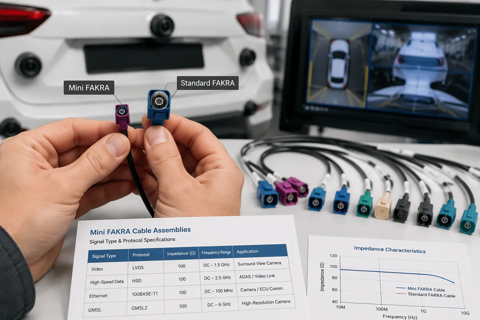
A camera link fails at the weakest point in the chain, not at the best component. Selection therefore follows a fixed order. Start with the interface and signal, then move to impedance, length, coding, pinout, orientation, shielding, and environment. This connector selection guide walks that path in sequence.
Interface, Signal Type, Protocol, and Data Rate
Signal type is your first filter. Confirm whether the camera outputs analog or digital video before you compare any connector. A digital link may support high bandwidth, long reach, robust EMC performance, low latency, and flexible topologies. Exact limits depend on the application, so confirm them with the supplier.
The protocol then narrows the harness content. Digital SerDes links often carry video plus control and diagnostics. Analog paths usually carry video only. Match the automotive camera cable to that content, and verify the vehicle camera system interface before you finalize the wiring.
As the automotive industry scales toward autonomous driving levels requiring uncompressed 4K video streams and instantaneous sensor fusion, the physical layer must adapt to the 12 Gbps threshold of the GMSL3 protocol. At these elevated frequencies, traditional interconnects become a bottleneck due to their physical size and high-frequency signal degradation. Consequently, next-generation architectures are heavily adopting the mini fakra standard as the baseline Automotive Camera Connector to ensure uncompromised data integrity along the gmsl cable. — Renhotecrf
Mini FAKRA suits compact multi-camera systems, found in surround-view modules, in-cabin camera clusters, and dense sensor nodes. The smaller body saves installation space and frees limited PCB real estate. It also cuts weight versus standard FAKRA. Do not assume Mini FAKRA is interchangeable with FAKRA in every application. Confirm the interface, protocol, and OEM requirements before committing.
Impedance, Length, Coding, Pinout, and Orientation
Impedance must stay consistent through the cable, the termination area, and the mating connector. A mismatch raises reflection and weakens video quality. Bafitoprf lists the split by link type:
Camera Link Type | Impedance Requirement |
|---|---|
FAKRA and HFM camera links | 50 ohm coaxial cable assembly |
HSD camera links | 100 ohm fully shielded differential connection |
Cable length drives insertion loss directly. A longer run adds loss at the operating frequency. Pair each length with its own loss budget. PCM Cable notes that a 5 m high-speed link cannot be validated by the DC–6GHz rating alone. Evaluate frequency, data rate, attenuation, return loss, and system margin together.
Coding and pinout come next. Match the key pattern to the receptacle, and confirm the pinout against the module drawing. Decide male or female, then straight or right-angle. A right-angle connector at the ECU end changes the effective length before the first bend, so show the exit path on the drawing.
Shielding, bend radius, and environment close the loop. A poorly terminated shield degrades EMC performance. Treat the connector, cable, crimp, adapter, and mating interface as one transmission channel. Check the minimum bend radius against the actual route. Then confirm vibration, moisture, and temperature exposure for the mounting location. Review Mini FAKRA connectors, automotive camera cables, custom cable assemblies, and FAKRA connectors against these cable selection factors before you release the drawing.
Why Cable Routing Matters in Multi-Camera Vehicles
Routing decides whether a good assembly survives the vehicle. A cable that passes bench tests can still fail after a tight bend or a long run beside a noise source. Plan the path before you lock the layout.
Bend Radius and Serviceability
Sharp bends damage the inner layers and shielding inside a coaxial cable. That damage weakens the signal and causes impedance mismatch. AC 43.13-1B sets the bend radius at no less than 6 times the cable outer diameter. A tighter target of 5x is the minimum, and 10x is best.
Routing Mistake | Impact on Signal | Recommended Practice |
|---|---|---|
Sharp bends in cable | Hurts inner layers and shielding, weakens signal and causes impedance mismatch | Keep bend radius at least 5x cable diameter (10x is best) |
Leave room for bend radius, mating access, connector release, and service handling before the layout is fixed. Bafitoprf notes that a high-density automotive connector only works well when the cable path around it stays manageable. For protected ECU interiors, routing space and access may matter more than sealing. Strain relief protects the termination from pull force. Service access lets a technician reach the connector without removing the camera.
Shielding Along the Route
Shielding must stay continuous from camera to ECU. A 360° termination captures the shield around its perimeter through compatible conductive hardware. A pigtail concentrates the connection into one wire, and its inductive reactance rises with frequency. Custom Wire Assembly gives an estimate of about 1.57 Ω at 10 MHz and 15.71 Ω at 100 MHz for a 25 mm pigtail at 1 nH/mm. Those are estimates, not measured shielding results.
Route the automotive camera cable away from motors, pumps, and power feeds. Celestix Industries reports a harness that passed CISPR 25 Class 5 emissions and immunity tests after using 360° shield termination and low-impedance grounding. Verify shield continuity after assembly with time domain reflectometry. Continuity checks alone do not prove EMC performance.
Mini FAKRA vs. FAKRA vs. HSD
Each of these three interfaces solves a different packaging problem. You cannot swap one for another at the harness level. The table below compares them on the points that decide a layout.
Attribute | Mini FAKRA | Standard FAKRA | HSD |
|---|---|---|---|
Size | Compact housing; quad-port versions save up to 80% of PCB space versus four single ports (Metabee) | Single-pin coaxial body with a larger shell | Four-pin shielded body |
Typical application | Dense multi-camera nodes | Single RF links such as radio, GPS, and camera | Differential data links |
Packaging requirements | Tight module spacing, short exit paths | More board area per port | Room for a four-pin bundle |
Coding options | Mechanical keying plus color | DIN 72594-1 poka-yoke keying; each keyway carries a standard RAL color | Keyed multi-pin housing |
Cable assembly considerations | 50 ohm coax, tight bend radius | 50 ohm coax, rated to 6 GHz | 100 ohm shielded differential cable |
Best-fit use cases | Surround-view and ADAS clusters | Legacy single-camera and antenna runs | USB and Ethernet-style links |
Size, Coding, and Packaging Differences
Mini FAKRA shrinks the housing and raises port density. Metabee reports that quad-port configurations save up to 80% of PCB space compared with four individual standard FAKRA connectors. Standard FAKRA uses a single-pin coaxial body. Metabee rates it to 6 GHz. HSD uses a four-pin shielded body for differential pairs.
Coding separates the families further. Standard FAKRA follows DIN 72594-1 poka-yoke keying, and each keyway carries a standard RAL color. A Keying A plug only fits a Keying A receptacle. Mini FAKRA adds its own key patterns and color cues. HSD relies on a keyed multi-pin housing instead.
Best-Fit Use Cases for Each
Choose Mini FAKRA when your camera module needs many ports in a small footprint. Choose standard FAKRA for single RF runs on platforms already built around it. Choose HSD when the link is differential and needs a shielded four-pin path.
Each option fits its own case. None replaces the others. Confirm the module interface before you order any fakra cable assembly.
Common Mini FAKRA Cable Selection Mistakes
Most failures in a multi-camera build trace back to the specification stage, not the factory. A wrong choice here costs rework later. The points below cover the errors that appear most often in this connector selection guide.
Appearance-Based and Coding Errors
Color is an identification aid, not proof of fit. The code letter and keying profile on the manufacturer drawing take priority over housing color. Per DIN 72594-1, each keying variant physically fits only into a matching receptacle of the same keying type. A blue plug from one supplier may not mate with a blue jack from another. Check the drawing before you order any fakra connectors.
Incomplete specifications cause most RFQ revisions. Buyers often omit the FAKRA code, connector gender, frequency band, or test reports, according to fakraconnectors.com. Others leave the cable exit undefined. Confirm coding, gender, orientation, cable type, length, impedance, shielding, environment, and quantity in writing. That single step prevents mismating, quotation delays, and installation problems.
Length, Shielding, and Termination Errors
An unsuitable length wastes loss budget or leaves slack that bends too tightly. Standard practice sets the bend radius at 8 times the cable outer diameter during installation, per fakraconnectors.com. Confirm the route can obey that figure before you release the drawing.
Termination errors hide well. Bafitoprf describes how a folded braid or uneven ferrule compression creates a reflection point near the termination. The cable can pass continuity and still fail at frequency. A crushed or sharply bent cable near the connector changes the spacing between center conductor and shield. A center contact cut too short or inserted at an angle can produce an intermittent signal when touched. Excessive stripping leaves a long uncontrolled section; insufficient stripping traps jacket or braid inside the crimp area. Inspect each termination under magnification, and confirm full connector lock with an audible click.
Installation and Inspection Checklist
Pre-Installation Verification
Run this checklist before any part reaches the vehicle. Verify the interface and coding against the module drawing. Confirm the pinout and the cut length. Inspect the shield and the crimp under magnification. Check the bend radius against the planned route. Confirm full lock at every mating point.
Match the key pattern on the connector to the receptacle before you attempt a mate.
Confirm the pinout and the cable length against the module drawing.
Inspect the shield termination and the crimp on each connector for folds or gaps.
Check the minimum bend radius of the cable against the actual route.
Confirm the latch clicks and the connector housing sits flush.
Key alignment sets the correct orientation, and the locking tab clicks audibly when fully engaged, according to Alibaba. Treat that click as a test result, not a sound. A connector can look connected without being fully locked. Bafitoprf warns that a cracked latch, a worn locking point, a bent plastic edge, or weak retention lets the connector move slightly on the module port. That small movement creates an intermittent RF fault in camera links.
Routing, Seating, and Final Checks
Route each cable before you seat the connector. Keep the run clear of sharp edges and heat sources. Leave slack for service access at the module end. Then push the connector housing home until the latch engages.
Inspect the latch area on every connector after seating. Bafitoprf notes that a housing which is not fully seated may pass a bench check, then turn unstable after vibration or harness movement. Recheck each vehicle camera connector after the camera module bolts down. A stable vehicle camera system depends on that final pass. Confirm each camera link, each fakra joint, and each mini fakra port once more before sign-off. Photograph each terminated connector and each routed cable. Order fakra connectors and cable assemblies from one supplier, and keep the inspection record with the harness drawing.
When to Choose a Custom Mini FAKRA Cable
A standard catalog part fits a standard route. Your multi-camera build rarely follows one. Choose a custom Mini FAKRA cable assembly when the module drawing, the body cavity, or the platform specification falls outside the catalog range. A custom build also makes sense when one harness must serve several camera positions at once.
Length, Branch, and Harness Variations
Non-standard lengths are the most common trigger. A rear camera may need a short run, while a side camera crosses the body to reach the ECU. Each run needs its own loss budget. A custom build lets you cut each leg to the measured route instead of adding slack loops.
Branches and breakout points drive the second decision. One trunk can split into several camera legs, and each leg ends in its own connector. That structure reduces total cable count and simplifies installation. Platform-specific requirements also count. A unique keying pattern, a right-angle exit, or a sealed jacket may not exist as a catalog item. LEADSIGN offers OEM and ODM support plus custom harness capability for these cases. Share your drawing early, and confirm the interface before tooling starts.
Prototype vs. Production Volumes
Prototype builds reward flexibility. You may change camera count, routing, or connector orientation between iterations. A custom camera cable assembly lets you test the real path before you commit to tooling. Keep each revision documented, so the next build starts from a known drawing.
Production volumes reward consistency. Once the design freezes, a custom fakra cable assembly locks the length, pinout, and shielding into one repeatable part. Volume affects lead time and cost, so discuss both with your supplier. Do not assume a custom part costs more at every quantity. Ask for a quote at your actual annual volume, and compare it against the catalog alternative.
What to Send LEADSIGN for a Quote
A clear request shortens the quote cycle for any camera harness. Send the released drawing, the BOM, the FAKRA code, the connector gender, and the mating connector. Add the frequency band, installed length, routing condition, and sample quantity. State your annual forecast and required reports, as roboticscableassembly.com advises. Attach the camera module drawing too.
Technical Inputs Buyers Should Provide
Write the impedance target down. Do not assume it. Most vehicle links run on 50 ohm coax, yet wireharnessproduction.com recommends stating that value explicitly. Name the application band as well: GPS, LTE, camera, or a multi-band path. The frequency window and cable attenuation must match your real use. A video camera link needs a wider window than a GPS feed.
A usable request defines five items before price: the approved keyed housing, the impedance target, the coax cable family, the installation environment, and the validation plan. Add the quantity split for prototype, pilot, and production, plus target lead time. Describe the routing zone, bend constraints, sealing exposure, and vibration risk. List every camera position, so each camera leg gets its own length.
Samples, Testing, and Documentation
Ask for first-article samples before releasing a production lot. A first-article VSWR sweep runs before each production lot proceeds, per oemcableassembly.com. Production then follows an AQL 1.0 lot sample resweep. Programs with tighter RF risk can add insertion-loss or return-loss checks through a qualified third party. A camera link with a long run deserves that step.
Category | Item |
|---|---|
Documentation | PPAP Level 3 on every NPI: dimensional report, capability study, IMDS submission, control plan, FMEA |
Testing | VSWR sweep per code and length, trace attached to the traveler |
Testing | LV 214 thermal-cycle and mating-cycle sample on first article |
Quality | IATF 16949 certified |
Common starting points include continuity, pin mapping, shield continuity, connector retention, and visual inspection, according to wireharnessproduction.com. Ask for a COC and revision-controlled build records. Then email your drawing to info@leadsignauto.com for a Mini FAKRA cable assembly quotation. Include the camera count, cable length, automotive camera cable part number, and vehicle camera system name. Confirm the system revision and connector drawing first. Order fakra connectors from one supplier.
Start with the camera interface and signal type. Then confirm impedance, data rate, length, coding, pinout, shielding, and environment. Verify compatibility at the module level, never by appearance alone.
The mini format, standard FAKRA, and HSD each fit different use cases. A documented checklist keeps your build consistent and reduces rework. That discipline protects every camera link in the vehicle camera system. Confirm each connector against the drawing before release. Check the connector lock too.
Need a custom mini fakra cable assembly? Email LEADSIGN at info@leadsignauto.com for a cable quotation. Draft your meta title at 55–60 characters and your meta description at 150–160 characters, and work "mini fakra cable" into both naturally.
FAQ
Can you use a Mini FAKRA cable on any automotive camera?
No. You must match the cable to the camera module interface first. Mini FAKRA is a distinct interface from standard FAKRA. Similar looks do not prove compatibility. Check the module drawing, the protocol, and the OEM requirement before you order any cable.
How do you know which coding your camera connector needs?
Read the module drawing. The key pattern and the code letter define the mate. Color is only a visual aid. Two housings can share a shade and still differ in key geometry. Confirm the code in writing before you release the connector to production.
What causes a camera link to fail after a good bench test?
Routing and termination cause most field failures. A tight bend damages the shield inside the cable. A weak crimp breaks shield continuity. A partly seated connector moves under vibration. Inspect each termination and confirm the latch click on every camera port.
When should you request a custom Mini FAKRA cable assembly?
Request a custom build when your route falls outside the catalog range. Non-standard lengths, branches, sealed jackets, and unique keying all justify one. A custom cable lets you cut each camera leg to the measured path instead of adding slack loops.
Does a longer camera cable always need a different part?
Not always, but length changes your loss budget. A longer run adds loss at the operating frequency. Pair each length with its own budget and confirm the result with your supplier. Do not assume one cable part covers every camera position in the vehicle.
See Also
Why Quad Mini Fakra Connectors Matter So Much In Cars
Discovering The Benefits Of Mini Fakra Connectors In Cars
Exploring The Benefits Of Mini FAKRA Connectors In Today's Cars
Revealing The Benefits Of Mini Fakra Connectors In Vehicle Systems
Harnessing The Power Of FAKRA Coaxial Cable Connectors Today