Automotive Telematics Cable Assembly: FAKRA Solutions for LTE and 5G Antennas

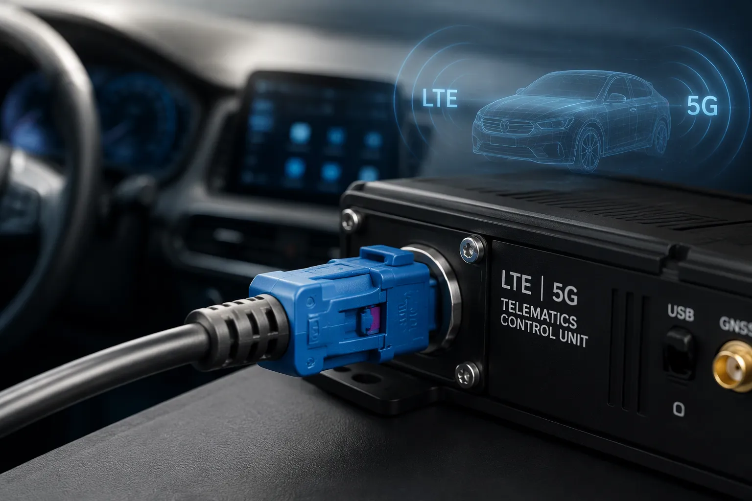
A wrong pick brings real trouble. Connector mismatch stalls the build. Poor routing and excessive length add signal attenuation. Installation problems surface later, after the vehicle leaves the line. FAKRA options help, but only when the specification matches the port.
In Short: Selection depends on port matching, cable route, specifications, layout, and protection level. Buyers should confirm the antenna interface, module interface, connector coding, and cable length before ordering any assembly for the vehicle.
Key Takeaways
Match the FAKRA connector's coding and gender to both the antenna and module ports to avoid installation errors.
Measure the actual cable route and add slack for service; avoid sharp bends to prevent signal loss.
Check that the assembly meets 50-ohm impedance and other RF specs for your specific build, not just the connector.
Choose sealed FAKRA options for exposed locations to protect against moisture and vibration.
Always review drawings and test samples before production to catch fit and performance issues early.
What Is an Automotive Telematics Cable Assembly?
Coax Cable and Connector Combination
An automotive telematics cable assembly generally combines an automotive coaxial cable with one or more connectors. The coax carries radio frequency signals with low loss. The connectors terminate each end and mate with the vehicle hardware. A fakra cable assembly uses FAKRA connectors as the interface standard for many vehicle communication links.
The exact design depends on several factors. These include the application, connector interface, cable type, length, routing space, frequency needs, environment, and vehicle architecture. A short run inside a dashboard differs from a long route to a rear-mounted antenna. Each build must match its own set of conditions.
Role Between Antenna and Module
The assembly links antennas and electronic modules across the vehicle. It connects a roof antenna to a telematics control unit, a wireless module, a GNSS receiver, a gateway, or an infotainment head unit. This automotive antenna cable assembly carries cellular, positioning, and data signals between those points.
Vehicle programs use these assemblies across many functions. Common applications include LTE and 4G communication, 5G connectivity, vehicle tracking, emergency call systems, fleet management, connected car services, GNSS and GPS positioning, Wi-Fi links, gateways, and infotainment. Each function places its own demands on the RF path. A telematics RF cable must suit the specific module and antenna pair. The fakra coaxial cable assembly format supports these links with a compact, keyed interface. Engineers confirm the interface and route before they release a drawing.
Why FAKRA Connectors Suit Telematics
Locking, Keying, and Coding
FAKRA connectors bring an automotive-oriented mechanical design to vehicle communication links. A primary lock and a secondary lock hold the connection secure against vibration. The keying and coding system reduces mismating during assembly. Each housing carries a mechanical key and a color code. LEADSIGN FAKRA products offer 13 colored codings plus one neutral coding. This arrangement helps technicians route the right cable to the right port and protects the rf link.
The coding does more than speed up installation. It prevents a cellular cable from landing on a GNSS port by mistake. A mismated pair can damage contacts or degrade the rf path. A coded pair also shortens line-side checks and reduces rework. Buyers should still confirm the coding against the module drawing. Suitability depends on the specific system and product configuration. Not every FAKRA connector suits every LTE, 5G, or telematics application.
Compact Vehicle Installation
Space inside a vehicle is tight. A compact automotive coax connector system fits behind trim panels and inside small module cavities. FAKRA housings come in multiple configurations for quick plug-in operation. Separate housings are also available. Right-angle and straight versions give layout freedom in narrow gaps. This flexibility helps engineers place an automotive fakra connector where a larger interface would not fit, and it keeps the rf interface close to the telematics module.
Verified LEADSIGN FAKRA facts support these vehicle demands. The interface maintains 50 ohm impedance and operates from DC to 6 GHz. It supports data rates up to 8 Gbps with return loss of at least 18 dB. The rated temperature range runs from −40 °C to +105 °C, with at least 25 mating cycles. Waterproof versions are available for exposed locations. These figures describe the connector family, not a guarantee for every assembly. The rf link still depends on cable type, length, termination quality, and rf performance. Engineers confirm the fakra cable assembly against the full vehicle system and technical drawing.
FAKRA Cable Assembly Selection for Telematics Modules
Connector Family, Gender, and Coding
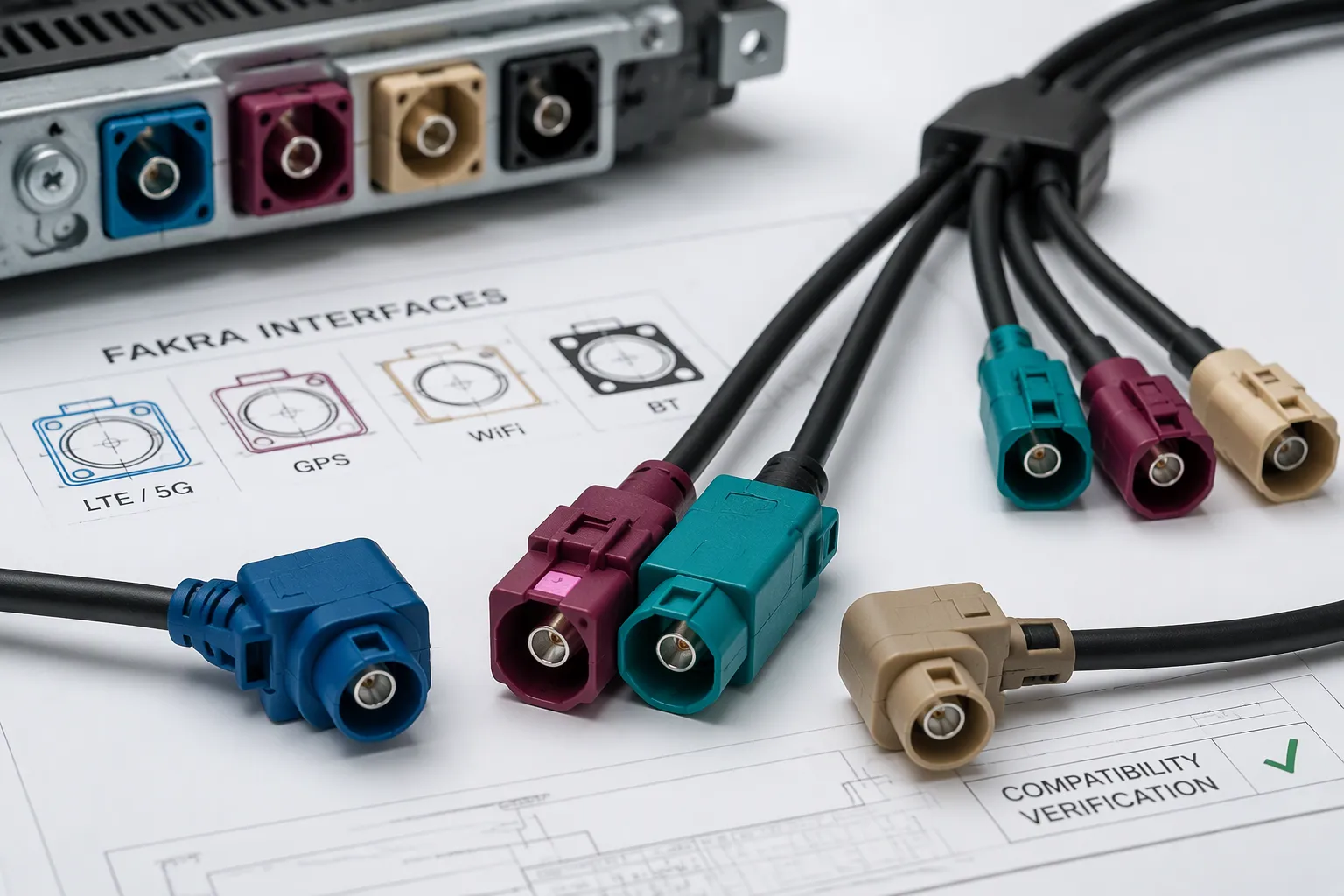
Selection starts with the connector family. Buyers confirm the fakra connector family matches both the antenna port and the module port. Gender comes next. A male pin connector mates with a female socket, and the reverse pairing fails at installation. Technicians should verify gender on both ends before release.
Coding and keying protect the rf path from mismating. Each fakra housing carries a mechanical key and a color code. LEADSIGN FAKRA products offer 13 colored codings plus one neutral coding. A cellular cable should not land on a GNSS port. The coding system prevents that error on the line. Buyers confirm the coding against the module drawing and the antenna drawing.
Selecting by appearance or color alone is not sufficient. Two housings may look alike but carry different keyways. A color match does not guarantee electrical compatibility. The fakra interface includes mechanical features that a visual check cannot confirm. Engineers should compare part drawings, not just product photos.
Final compatibility must be confirmed against the vehicle system and technical drawing. The mating connector on the module or antenna defines the required interface. A fakra cable assembly selection for telematics modules depends on that confirmed pair. Buyers should request drawings for both sides before ordering.
Housing, Orientation, and Branch Configuration
Housing configuration shapes the installation. Buyers choose between straight and right-angle designs based on space and cable exit direction. A right-angle housing turns the cable along the module face. A straight housing sends the cable away from the port. The cable exit direction must match the route plan.
The number of connectors and the branch configuration also matter. A single-ended assembly carries one connector at each end. A multi-branch design splits one run into several legs. Multi-branch builds suit vehicles with multiple antennas and multiple rf paths. Each branch needs its own confirmed interface.
Configuration | Typical Use | Confirmation Point |
|---|---|---|
Single-ended, straight | Direct module-to-antenna run | Port depth and cable exit |
Single-ended, right-angle | Tight cavity behind trim | Bend clearance at housing |
Multi-branch | Several antennas, one module | Coding per branch |
Buyers should confirm the mating connector on the module or antenna for every branch. An automotive fakra connector that fits one port may not fit another. The housing key, the gender, and the cable exit all affect fit. A drawing review catches these issues before production.
The fakra cable assembly must also match the vehicle architecture. Space limits, routing paths, and service access vary by program. Engineers should share the route plan with the supplier. The supplier can then confirm the housing and orientation against the drawing. Final compatibility still rests with the vehicle system and technical drawing. No catalog image replaces that check.
Choosing Coax Cable for the Vehicle Route
Measuring Route Length
Length starts with the real path, not a straight-line estimate. A technician traces the cable from the antenna base to the telematics control unit. The trace follows every bracket, panel, and trim gap along the way. This method captures the true distance the cable must travel.
The measured path should include room for service movement. A cable needs slack for installation and later maintenance. Excess unused cable creates its own problems. Coiled loops waste space and can press against sharp edges. The route should avoid tension at the connector and any crushing point. Engineers also weigh the antenna and TCU positions early, since a small layout change can shift the whole run. Longer assemblies can introduce additional attenuation, so the shortest practical route usually serves the rf link best. A confirmed fakra cable assembly drawing should reflect the final measured path.
Bend Radius and Strain Relief
Every coax cable has a minimum practical bend radius. A tight fold can crush the dielectric and change the rf performance. The installer should confirm that radius against the cable datasheet before routing. Sharp corners near a bracket deserve special attention. A gentle curve protects the fakra connector and keeps the signal path stable.
Strain relief protects the termination point. The cable should not hang its weight on the connector body. A clamp or tie near the housing carries that load instead. Movement from vibration and service work then stays away from the rf joint. These habits support long-term automotive reliability. A well-routed fakra cable assembly resists pull, flex, and vibration over years of vehicle use.
Checking FAKRA Cable Assembly Specifications
Impedance, Return Loss, and Shielding
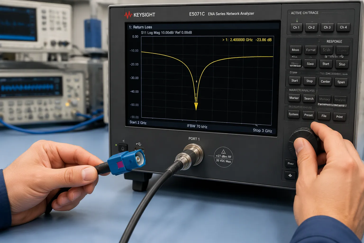
A specification review starts with impedance. Many automotive RF applications use 50 ohm impedance as the baseline. This value keeps the signal path matched from the antenna to the module. A mismatch at any point reflects energy back toward the source. The result is a weaker signal at the receiver and a less stable link.
Return loss measures how well the assembly resists those reflections. A higher return loss value indicates a cleaner match. LEADSIGN FAKRA products state a return loss of at least 18 dB across the connector family. That figure describes the connector, not the finished assembly. The full fakra cable assembly specs depend on the cable, the termination, and the length. Engineers should request assembly-level data for the exact build.
Shielding effectiveness protects the RF path from outside interference. A vehicle carries many noise sources, from motors to power electronics. A well-shielded coax keeps those signals out of the telematics link. The shield also keeps the RF signal inside the cable, where it belongs. Buyers should confirm the shield construction and the connector-to-cable bond.
Insertion loss describes signal energy lost along the run. Every cable, connector, and joint adds some loss. A longer assembly generally adds more loss than a short one. Routing and bending also affect performance. A crushed cable or a tight bend can change the impedance and raise loss. Performance depends on cable, connector, assembly length, installation method, and system design. No single number covers every build.
Termination and Cable Compatibility
Correct termination joins the connector to the cable with a stable electrical and mechanical bond. A poor crimp or a loose ferrule raises resistance and weakens the RF path. The termination must match the cable type. A connector designed for one coax family may not fit another. Buyers should confirm that the connector and cable come from a compatible pair.
The 50 ohm impedance must hold through the termination zone. A gap or a stray wire at the joint creates a local mismatch. That mismatch can degrade the 50 ohm RF path even when the cable itself is sound. A qualified automotive RF cable assembly uses a controlled termination process. The supplier should document that process and the cable it supports.
Cable compatibility also covers the jacket and the dielectric. The jacket must suit the vehicle environment. The dielectric must hold its properties across the temperature range. LEADSIGN FAKRA products are rated from −40 °C to +105 °C. That rating applies to the connector family. The assembly must still be confirmed as a complete unit.
A final check covers the drawing. The drawing should list the connector, the cable, the length, and the coding. It should also note the bend radius and the strain relief plan. Buyers who review these details catch problems before production. Final compatibility must be confirmed against the vehicle system and technical drawing.
Straight vs. Right-Angle FAKRA Connectors
Clearance and Connector Access
A straight fakra connector sends the cable directly away from the port. This layout works well when the module sits in open space. The installer gains a clear path to push the plug home. A straight body also gives the hand a firm grip during mating. The trade-off appears when a panel or bracket sits close behind the port. The cable then needs room to turn, and that turn consumes clearance.
A right-angle fakra connector turns the cable parallel to the module face. This design suits shallow cavities behind trim. The cable exits along the housing instead of away from it. Technicians gain access in spots where a straight plug would collide with nearby structure. The right-angle body also keeps the fakra cable assembly close to the panel surface. Engineers should confirm the exit direction against the route drawing before release.
Consideration | Straight | Right-Angle |
|---|---|---|
Installation space | Needs depth behind the port | Needs lateral room along the face |
Cable routing | Runs away from the module | Runs parallel to the module |
Clearance | Demands open space at the rear | Fits shallow cavities |
Connector access | Easy push and pull in open areas | Better reach in tight trim gaps |
Mechanical strain | Load pulls straight on the joint | Bend sits close to the housing |
Tight packaging | Less suited to shallow recesses | Well suited to confined spaces |
Typical selection | Open dash areas, serviceable ports | Narrow gaps, hidden modules |
Mechanical strain Considerations
Each orientation loads the joint in its own way. A straight fakra connector takes pull along its axis. A clamped cable keeps that load off the rf joint. A right-angle fakra connector redirects the cable at the housing. The bend point then carries more stress during vibration. A proper strain relief tie near the body protects the rf path in both cases.
Neither option wins on every build. The right choice follows the route, the cavity depth, and the service plan. Engineers should match the fakra connector to the drawing and confirm the rf layout with the supplier. The fakra cable assembly then fits the automotive telematics system as designed.
LTE, 4G, and 5G Antenna Architectures
Multiple Antennas and RF Paths
Newer connected-vehicle systems may use several antennas and several RF paths. A single roof pod can hold cellular elements, a positioning element, and a Wi-Fi element. Each element feeds its own RF port on the telematics control unit. The assemblies must match the specific vehicle architecture. A 5g telematics antenna cable built for one port may not suit another.
Cellular communication drives much of this complexity. An LTE antenna cable carries the main link, and a second cable may serve diversity. A 5G path adds its own demands on the RF chain. Engineers should treat each path as a separate design task. They confirm the interface, the coding, and the route for every leg. A standard fakra cable assembly does not automatically support every 5G system. Suitability depends on the confirmed system and product configuration.
GNSS, Wi-Fi, and Gateway Links
Positioning and data links share the same vehicle space. A GNSS cable assembly feeds the receiver with a clean RF path. A Wi-Fi link serves updates and hotspot traffic. Gateways and TCUs collect these signals and pass them along the vehicle network. Each link needs its own confirmed interface specification.
Space and routing limits shape the layout. Multiple cables compete for the same trim gaps and bend zones. Engineers should plan the bundle early and keep each RF path clear of sharp bends. They also confirm every mating port against the drawing. These telematics RF links only perform well when each assembly matches its port, its route, and its environment. A fakra interface helps organize the connections, and the drawing remains the final authority.
Protection Level and Environmental Fit
Sealed and Waterproof FAKRA Options
A vehicle exposes every cable to a hard life. Vibration shakes the joint. Temperature cycling expands and contracts each material. Moisture and dust find their way into trim gaps. Mechanical movement, bending, and pulling add stress over years of operation. A sealed fakra cable assembly answers these conditions at the connector interface.
Waterproof FAKRA versions are available for exposed locations. These designs add sealing at the housing and around the terminal zone. A sealed fakra cable assembly keeps moisture away from the rf joint. Buyers should confirm the sealing requirement for each mounting point. A cabin module and a roof antenna face very different exposures. The locking structure also matters here. A primary and secondary lock holds the pair together under vibration. The terminal design must resist corrosion and movement. Engineers should confirm all of these points against the project drawing.
Temperature, Vibration, and Jacket Material
Temperature range sets the first limit. LEADSIGN FAKRA products are rated from −40 °C to +105 °C. That figure covers the connector family, not every finished build. The jacket material must suit the same range and the local environment. A jacket that hardens in cold weather can crack at a bend. A jacket that softens in heat can sag against a hot panel.
Vibration and long-term operation test the whole assembly. A rugged fakra cable assembly uses a stable termination and a secure lock. Buyers should confirm the validation requirements for the specific project. They should also confirm the jacket material, the sealing plan, and the terminal design. LEADSIGN FAKRA products are stated as RoHS, WEEE, and ELV compliant. Buyers should not assume other compliance without verification for the exact product. Final fit still rests with the vehicle system and technical drawing.
Standard vs. Custom FAKRA Cable Assemblies
When Standard Assemblies Fit
A standard assembly suits programs with predictable needs. The connector combination is common, and both the antenna and module ports use familiar interfaces. The cable length is known and stable across builds. Routing follows a regular path with no unusual bends or tight cavities. Buyers order the same fakra cable assembly again and again, so tooling and drawings already exist.
Repeated purchasing rewards this approach. A catalog fakra connector pair shortens lead time and simplifies inventory. The buyer can compare options from stock and confirm the interface against the module drawing. Standard builds also fit common antenna and module interfaces found across many vehicle platforms. Engineers should still verify coding, gender, and length before release.
When Custom Configurations Help
Custom work fits programs where a catalog part falls short. A special length may be needed to follow an unusual route. Different connector types may sit at each end, such as a straight plug on one side and a right-angle plug on the other. Special coding, limited installation space, or a multi-branch design all point toward a custom build. Prototypes, low-volume projects, OEM integration, and aftermarket electronics often need this flexibility.
LEADSIGN supplies FAKRA connectors, FAKRA coaxial cables, FAKRA cable assemblies, FAKRA extension cables, FAKRA adapters, HSD connectors and assemblies, and Mini FAKRA solutions. Customers can share their application, interface, length, configuration, coding, and routing requirements for evaluation. Buyers who need a tailored fakra coaxial cable assembly can request a drawing review before quoting. Related options include custom FAKRA cable assemblies, Mini FAKRA connectors, and HSD cable assemblies for high-speed data links. A custom fakra connector layout keeps the rf path matched to the vehicle. Final compatibility still rests with the vehicle system and technical drawing.
Interface Adapters and Test Setups
FAKRA to SMA Adapters in Bench Testing
Bench work often starts before the vehicle build. A lab bench uses test equipment with SMA ports. The module under test carries a fakra port. A set of fakra to sma adapters bridges the two sides. The engineer connects the adapter to the module, then runs a test cable to the analyzer. This setup lets the team check the rf path without a full harness.
Prototype evaluation follows the same pattern. An engineer mounts a sample assembly on the bench and measures its rf behavior. Fakra to sma adapters make that measurement possible. The lab can sweep the link and log the result. A second round of fakra to sma adapters may serve the antenna side. The team then compares both ends of the rf chain.
Bench testing also supports design reviews. The engineer swaps cables and repeats the test. Fakra to sma adapters speed up each change. The team can screen several fakra cable builds in one session. This early work catches rf problems before tooling. It also gives the buyer data for the drawing review.
Confirming Mating Interfaces
Adapters serve test and interface conversion only. They do not replace the production mating interface. A bench pass through fakra to sma adapters proves the rf path, not the vehicle fit. The production fakra interface must still match the module port and the antenna port. Engineers should confirm that pair on the drawing.
The final check covers gender, coding, and keyway. A test adapter may accept any fakra plug. The vehicle port will not. Buyers should treat the adapter as a lab tool and the drawing as the authority. A confirmed fakra interface protects the automotive telematics build. Teams should verify each rf port before release.
Procurement Checklist for Buyers
Specification and Interface Details
A complete specification prevents most ordering errors. Buyers should record every interface detail before they request a quote. The table below lists the points that matter most for a fakra cable assembly.
Specification | Why It Matters | Information to Confirm |
|---|---|---|
Application | Defines the RF path | LTE, 5G, GNSS, or Wi-Fi function |
Vehicle system | Sets the architecture | Antenna and module positions |
Antenna interface | Prevents mismatch | Connector family and gender |
Module interface | Prevents mismatch | Mating fakra connector type |
Connector family | Ensures fit | FAKRA or Mini FAKRA |
Gender | Ensures mating | Male or female on each end |
Coding | Prevents mismating | Color and keyway |
Cable type | Sets RF performance | Coax family and jacket |
Cable length | Controls attenuation | Measured route distance |
Connector orientation | Fits the cavity | Straight or right-angle |
Cable exit direction | Fits the route | Direction away from port |
Number of cable ends | Defines the build | Single or multi-branch |
Branch configuration | Matches antennas | Leg count and coding |
Shielding | Blocks interference | Shield construction |
Environmental conditions | Sets protection | Sealing and temperature |
Buyers should confirm 50 ohm impedance and the full fakra cable assembly specs against the drawing. A 5g telematics antenna cable needs the same review as an lte antenna cable or a gnss cable assembly.
Samples, Drawings, and Delivery
Samples and drawings close the loop before production. Buyers should request a sample of the exact build and test it on the vehicle. A drawing review confirms gender, coding, and length. The drawing also records the cable exit direction and the bend plan.
Delivery terms deserve the same attention. Buyers confirm quantity, packaging, and lead time in writing. A clear purchase order protects both sides. Final compatibility still rests with the vehicle system and technical drawing.
Common Selection Mistakes to Avoid
Connector and Coding Errors
One common error starts with a photo. A buyer picks a fakra connector by appearance and skips the drawing. Two housings can look alike and still carry different keyways. Color alone does not prove compatibility. The fakra coding exists for this reason. Ignoring the coding invites a mismated pair on the line. A mismated pair can degrade the rf link. Confusing male and female interfaces causes the same result. The plug simply will not seat on the module port.
Another mistake pairs the wrong connector with the module. A housing that fits one port may not fit another. Buyers should confirm the antenna interface before release. They should also avoid assuming that all fakra cable assemblies share the same rf performance. Cable type, length, and termination all shape the rf path. The rf chain depends on the full build. A bench pass on one build says little about the next. Buyers should compare rf data, not photos. Each fakra assembly deserves its own rf review against the drawing.
Length, Routing, and Documentation Errors
Length errors surface at installation. A short estimate leaves the cable under tension. An oversized run adds attenuation and wastes space. Ignoring routing space forces sharp bends near brackets. A tight fold can crush the dielectric and disturb the rf signal. Pulling the cable by the body loads the rf joint. A clamp near the fakra housing carries that load instead. The rf path stays stable with a gentle curve.
Documentation gaps cause quiet failures. Some buyers skip drawings and samples and order from a catalog image. A sample test on the vehicle catches fit problems early. Missing production details create their own delays. Packaging, quantity, and delivery terms belong in the purchase order. A confirmed drawing protects the telematics build. It also keeps the automotive line moving. Engineers should treat the drawing as the final authority for every fakra interface and every pair of antennas. The rf layout should appear on that drawing.
A sound selection follows a fixed sequence. Buyers can treat these steps as a working checklist:
Define the application and the vehicle function.
Match the port, gender, and coding on both ends.
Size the cable to the measured route.
Verify the rf specifications for the exact build.
Fit the layout, including orientation and bend clearance.
Set the protection level for the mounting location.
Final compatibility must be confirmed against the vehicle system and technical drawing. The right automotive telematics cable assembly depends on application fit, not on a single best option. Each fakra cable assembly serves its own port, route, and environment.
Readers can contact LEADSIGN at info@leadsignauto.com for product information, technical consultation, sample evaluation, custom configuration, and quotations. The official website lists fakra connectors and cable assemblies for review.
FAQ
Which FAKRA coding should a buyer confirm first?
The buyer confirms the fakra coding against the drawings. The rf port on the module sets the rf keyway. The rf port on the antenna sets the rf match. A wrong rf code blocks the rf plug. The rf check settles the rf question. The rf drawing stays the rf authority.
How does cable length affect the RF link?
The fakra cable length adds rf loss. A long rf run weakens the rf signal at the rf module. The rf team measures the real rf route. Extra rf cable adds rf loss. A short rf path protects the rf link. The rf plan should match the rf drawing.
Do straight and right-angle FAKRA connectors perform the same?
Both fakra styles carry the rf signal. The rf difference comes from the rf route, not the rf body. A right-angle fakra bends the rf cable near the rf housing. That bend adds rf strain. The rf team confirms the rf bend radius. The rf drawing should show the rf exit.
What should a buyer check before approving a sample?
The buyer tests the fakra sample on the vehicle. The rf check covers the rf fit, the rf coding, and the rf route. The rf team logs the rf data. A failed rf fit sends the rf build back to the rf drawing. The rf sample proves the rf design.
Can one FAKRA assembly serve LTE, 5G, GNSS, and Wi-Fi ports?
No. Each fakra port carries its own rf role. The rf team confirms the rf interface for every rf path. A 5G rf link may need a different rf build. The rf drawing lists each rf port. A fakra assembly rarely covers every rf function.
See Also
Improving Automotive Data Transfer Using FAKRA PCB Connectors
Advantages of Fakra Antenna Adapters for Automotive Infotainment Systems
Realizing the Potential of High-Speed FAKRA-Mini Connectors in Automotive
Boosting Automotive Communication Through FAKRA PCB Connectors