FAKRA to SMA Adapter for GPS and GNSS Antennas: Selection Guide

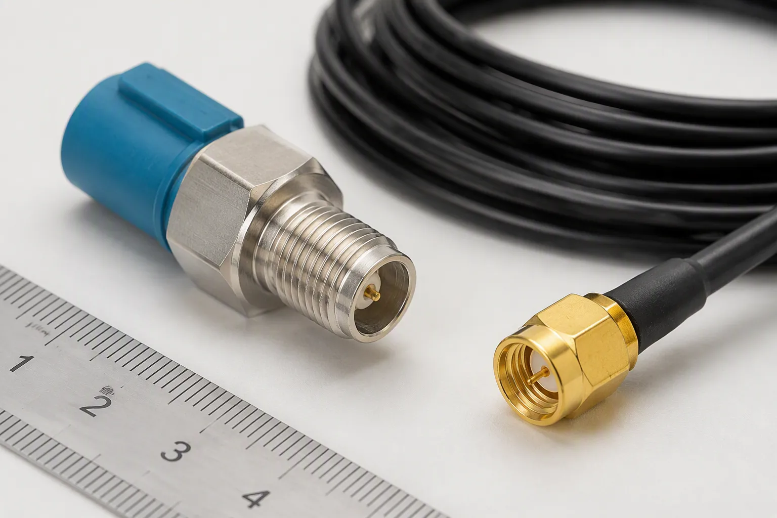
You have an automotive GPS antenna with a FAKRA connector. Your telematics box or test receiver uses an SMA port. A FAKRA to SMA adapter bridges these two interfaces. It connects the automotive side to an SMA interface on a GPS antenna, test device, receiver, telematics box, or RF module. Before you order, confirm several key details. Check the coding and color first. Verify the connector gender next. Confirm impedance, cable length, and connector orientation. You also need the frequency range, application, and mating devices. These details prevent mismating and signal loss in your setup. A wrong choice can block your signal.
Key Takeaways
Check the FAKRA code and color first. Code C (blue) is for GPS. This prevents wrong connections.
Verify SMA gender and polarity. Standard SMA and RP-SMA do not mate. A wrong match blocks your signal.
Match impedance at 50 ohms and use the right frequency range. This keeps your GPS signal strong.
Choose the correct cable type and length. Shorter cables and good shielding reduce signal loss.
Confirm all details before you order. This protects your equipment and ensures reliable performance.
What Is a FAKRA to SMA Adapter?
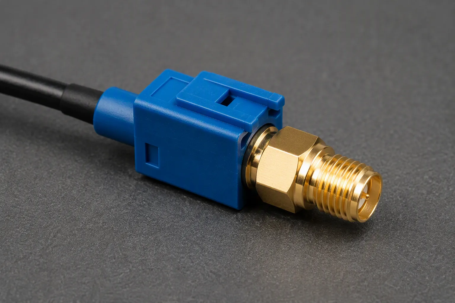
TL;DR: A 50-ohm bridge links an automotive RF interface to an SMA-equipped device. It is used for GPS antenna connection, receiver testing, and telematics integration. Buyers must confirm the code, gender, impedance, and cable details before ordering. A wrong choice can block your signal or damage equipment.
Definition and Role in RF Systems
This converter joins two different RF worlds. One end matches the snap-lock system found in vehicles. The other end connects to threaded SMA ports on test gear and receivers. This connector type operates at 50 ohms on both sides. The 50-ohm impedance matches the design requirement of GPS systems. GPS signals arrive at very low power levels. Signal quality depends on every connection along the path. A poor choice can introduce loss and degrade performance.
The vehicle-side interface uses color coding to prevent errors. Code C, which is blue, is designated for GPS antenna applications. This coding helps you identify the correct port during assembly. Do not confuse this 50-ohm RF system with HSD connectors. HSD uses a 100-ohm differential design for high-speed data. Mixing them causes signal failure or equipment damage.
Common uses include GPS antenna connection, GNSS receiver testing, telematics development, aftermarket installation, and prototype validation.
FAKRA vs. SMA: Key Differences
The two types differ in several important ways. The table below summarizes the key distinctions.
Feature | Automotive Connector | |
|---|---|---|
Coupling mechanism | Threaded nut, requires torque | Push-on snap-lock with click |
Locking security | Can loosen under vibration | Primary latch plus secondary lock |
Vibration resistance | Moderate | High, for automotive use |
Mating speed | Slower, requires threading | One-handed in seconds |
Error-proofing | Universal, no keying | Mechanical keying and color coding |
Durability | 500 mating cycles | 100 mating cycles |
Housing footprint | Smaller | Larger due to plastic housing |
The coupling mechanism is the most obvious difference. SMA uses a threaded nut that needs torque to secure. The automotive version uses a push-on housing that clicks into place. In vehicles, vibration can loosen threaded connections. The secondary lock prevents this.
Frequency range also differs.
Use the automotive connector for applications up to about 6 GHz. Use SMA for 4 to 18 GHz and higher in test equipment.
The error-proofing feature is another key advantage of the automotive connector. Its mechanical keying and color coding prevent you from plugging into the wrong port. This is critical in vehicle wiring harnesses where many RF ports sit close together. When selecting your GPS antenna adapter, always verify both ends match your equipment specifications.
GPS & GNSS Antenna Guide: Why Adapters Are Used
Weak Signals and the Need for Low-Loss Connections
GPS and GNSS signals arrive at your antenna with very little power. These signals travel thousands of miles from orbit. By the time they reach your vehicle, the signal is extremely weak. Every connection in the chain matters. Cable loss, adapter quality, shielding, and connector termination all affect the final signal. A poor adapter can degrade your GPS/gnss connectivity.
Cable loss adds up quickly. Standard RG174 cables lose signal strength with every meter of length. In the long run, the signal reaching your receiver can drop enough to cause position drift. That signal loss is the exact reason active antennas with a built-in low-noise amplifier exist.
Optimized for GPS Signal Integrity: Utilizes 50-ohm RG174 coaxial cable specifically chosen for its low loss at the GPS L1 frequency (1575.42 MHz). This ensures minimal signal degradation, preserving the accuracy and reliability of your navigation or tracking system.
The table below shows typical attenuation for RG174 cable at the GPS L1 frequency.
Cable Type | Frequency | Attenuation | Typical Length | Notes |
|---|---|---|---|---|
RG174 | 1575 MHz (1.575 GHz) | ~1.5 dB/m | 1.5–5 m | Used in vehicle GPS antenna with FAKRA (blue) connector |
RG174 | 1575 MHz (1.575 GHz) | ~1.2–1.5 dB/m | 2–3 m | — |
RG174 | 1575 MHz (1.575 GHz) | ~1.5 dB/m | — | Flexible, low-cost, higher loss; operating temp -20 to +70 °C |
Active vs. Passive Antennas and DC Pass-Through
Active vs. passive antennas differ in one critical way. Active GPS antennas require power through the coax. The receiver sends DC voltage up the cable to power a built-in amplifier. Active GPS antennas typically receive 3.3V or 5V DC power from the receiver through the coaxial cable. Your adapter must support DC pass-through if you use an active antenna. A passive antenna does not need power. It sends the signal directly without amplification.
You will find these adapters in many applications. Common uses include GPS antenna connection, GNSS receiver testing, telematics development, aftermarket installation, and prototype validation. Each application may need a different adapter configuration. Always confirm your antenna type before ordering.
FAKRA Side: Coding, Color, Gender, and Orientation
Automotive Standard: FAKRA Code C and Other Key Codes
The FAKRA coding system uses colors and mechanical keying. This prevents mismating. Each color has a unique rib configuration. DIN 72594-1 defines this Poka-Yoke design. Technicians handle many similar-looking fakra cables on assembly lines.
For GPS navigation, the automotive standard: fakra code c is used. This code uses a signal blue housing. The frequency range is 1.2–1.6 GHz. The mechanical key blocks non-matching connectors. Always verify your fakra c blue connectors against a drawing or photo.
Color | Application |
|---|---|
Blue | GPS antenna |
Green | Rear-view camera (LVDS) |
Red | AM/FM radio antenna |
White | Bluetooth/Wi-Fi |
Black | General RF signals |
Yellow | Satellite radio |
Do not trust color alone. The mechanical keying is the primary safeguard.
Gender, Straight vs. Right-Angle, and Mini FAKRA
Gender matters on the fakra c side. You need a male or female connector. Most fakra c connectors on antennas are female. The cable typically has a male connector. Confirm the connector type with your equipment. The fakra c keying prevents mismating.
Orientation also matters. Straight connectors work in open spaces. Right-angle connectors fit in tight areas. Choose a right-angle adapter for limited room to reduce cable stress.
Mini FAKRA is a smaller variant with 50-ohm impedance in a compact housing. Adapters to SMA require careful selection. The keying and color system differ from standard FAKRA. Do not assume Mini FAKRA fits standard ports. Verify with a drawing or sample.
The fakra c blue standard is your starting point for GPS. Confirm gender and orientation. Also confirm your fakra c blue adapter matches your equipment. Test your connections before final installation.
SMA Side: Male, Female, and RP-SMA
Standard SMA vs. RP-SMA Polarity
Standard SMA and RP-SMA look similar on the outside. Their threaded bodies match. The center contacts differ. A standard sma male connector carries a protruding pin. A standard sma female carries a recessed socket. RP-SMA reverses this arrangement. An RP-SMA male holds a socket. An RP-SMA female holds a pin. The threads may fit together, but the center contacts will not connect. This causes RF signal failure.
Connector Type | Center Contact |
|---|---|
Standard SMA Male | Pin |
Standard SMA Female | Socket |
RP-SMA Male | Socket |
RP-SMA Female | Pin |
Manufacturers developed RP-SMA for consumer wireless gear. The design stops users from attaching standard high-gain antennas. RP-SMA and standard SMA lack interoperability. For GPS tracking modules, the correct polarity keeps the RF path intact. A mismated pair blocks the weak satellite signal. Check the center contact before you connect anything.
Matching SMA Gender to the Mating Device
You must verify the sma gender on your GPS/GNSS antenna, receiver, or test equipment. Do not trust naming conventions alone. Inspect the connector by hand when documentation is missing. A sma male shows a pin plus external threads. A sma female shows a socket plus internal threads. This rule of thumb works on most hardware.
A sma male connector also needs a pin length check. A pin that sits too long can smash the delicate fingers of a female socket. Use a precision connector gauge when you mate with 3.5 mm ports. Look at the body shape too. A female PCB mount has a flat square base with four corner holes. A male cable connector has a round body with a spinning hex nut. Confirm the sma connector type on both ends before you order. This step protects your equipment and preserves signal quality.
Cable Length, Shielding, and Signal Loss
GPS signals arrive at your antenna with very low power. Every connector and cable in the path adds loss. Longer cables and poor shielding degrade the signal. You must confirm cable type, cable length, shielding, and impedance. Impedance must match at 50 ohms on both sides.
Choosing Cable Type and Length for GPS/GNSS
The cable type you choose affects signal quality. RG174 is a common choice for FAKRA to SMA GPS adapter assemblies. This cable is thin, flexible, and low-cost. It works well for short runs in applications like automotive telematics. RG174 operates up to about 1 GHz. That covers the GPS L1 frequency at 1.575 GHz. Pasternack offers FAKRA to SMA cable assemblies using RG174 coax with heat shrink. One example is the Fakra C Female to SMA Male Right Angle RG174 15cm GPS cable. These assemblies provide reliable connections for GPS applications.
RG316 offers better performance. It handles higher temperatures and provides better shielding. Use RG316 in under-hood or outdoor installations. This cable operates up to about 3 GHz.
For longer runs, consider low-loss options like LMR-100. LMR-100 provides 40 dB of shielding effectiveness. This level prevents electromagnetic interference from disrupting your GPS signals. The trade-off is larger size and less flexibility compared to RG174.
Cable length matters. Keep the cable as short as your installation allows. Every meter of RG174 cable adds about 1.5 dB of loss at the GPS L1 frequency. A 3-meter cable adds over 4 dB of loss. That loss reduces the signal before it reaches your receiver.
Shielding and Termination Quality
Shielding protects weak signals from GPS antennas from external noise. A good FAKRA to SMA adapter uses cable with adequate shielding. LMR-100 provides 40 dB of shielding. This level is adequate for GPS applications.
Termination quality also matters. Poorly terminated connectors introduce signal reflections. Look for assemblies with proper heat shrink at the connector joints. FAKRA to SMA cable assemblies often use RG174 coax with heat shrink for strain relief. This protects the connection from vibration and pulling forces.
Your adapter selection must confirm shielding and termination quality. A well-shielded assembly preserves your GPS signal integrity.
Common Use Cases: Telematics, Testing, Retrofit
Telematics and Infotainment Integration
During telematics development, you connect a factory GPS unit to test equipment. The vehicle uses a FAKRA blue C connector. Your spectrum analyzer or GNSS simulator uses an SMA port. A FAKRA to SMA adapter bridges this gap.
This setup lets you validate receiver performance without modifying the vehicle harness. You capture real satellite signals through the OEM equipment. The adapter maintains the 50-ohm path. Signal integrity stays intact for accurate testing.
For infotainment systems, you may add a third-party navigation module. Most aftermarket GPS trackers use SMA connectors. Factory car stereos from Ford, BMW, VW, Audi, and Mercedes use FAKRA blue C for GPS. This mismatch creates a need for an adapter. The adapter preserves oem car stereo compatibility while adding your new device. Without it, you would replace the factory GPS unit entirely.
A typical setup uses a short HFC RG‑316/U cable with FAKRA on one end and SMA on the other. The length stays at 20 cm to minimize loss. The adapter connects the factory GPS unit to your new telematics box. This short cable run keeps signal degradation low at the GPS L1 frequency.
Aftermarket Retrofit and Prototype Validation
Retrofitting a GPS receiver into an older vehicle requires careful connector planning. Many cars from Audi, BMW, Citroën, Fiat, Ford, Jaguar, Jeep, Kia, Land Rover, Mercedes‑Benz, Opel, Porsche, Range Rover, Renault, Peugeot, Seat, Skoda, Volvo, and Volkswagen use FAKRA for the factory GPS antenna. Your aftermarket navigation box likely has an SMA port.
You screw the GPS unit SMA connector onto the adapter SMA jack. Then you snap the FAKRA connector onto the GPS port on the back of the receiver. The signal blue type C FAKRA keying matches GPS applications only. This ensures you connect to the correct port.
This approach works with both active and passive GPS antennas. Active units require DC pass‑through through the adapter. Passive units do not. Verify your unit type before ordering. The adapter lets you choose from many GPS units with SMA male connectors pre‑installed.
During prototype validation, you test new hardware with existing vehicle GPS units. The adapter lets you swap between different GPS receivers quickly. You avoid cutting or replacing the factory cable. The connection remains reliable for bench testing and in‑vehicle trials. The adapter supports development cycles without permanent vehicle changes.
How to Specify a Custom FAKRA to SMA Adapter
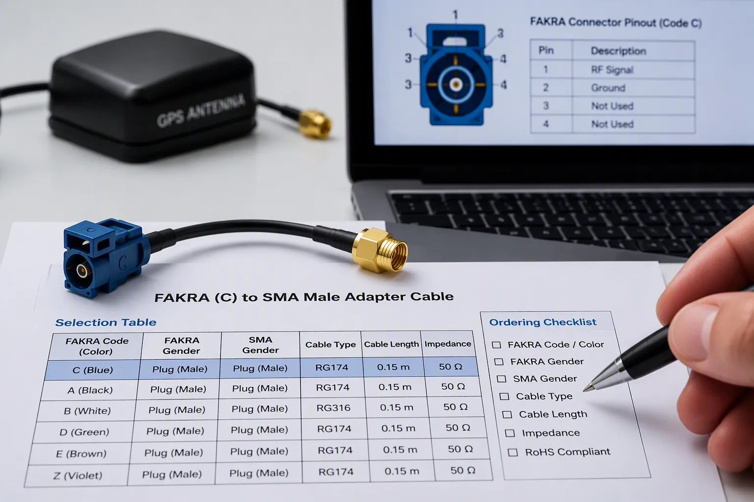
Information Buyers Must Provide
A custom adapter order succeeds or fails on the details you supply. Start with the application context. Tell the supplier the equipment, vehicle, device, or system involved. Describe the intended function and the installation location. This information shapes every other decision.
Next, provide approved connector part numbers. Include gender, coding, keying, and any acceptable alternatives. The FAKRA system uses codes A through N plus Z. Each code carries a distinct color and keying position. Code C is blue and serves GPS. Code A is black. Code Z is water blue and works as a universal type. State the exact code you need.
Define the electrical path. A pin-to-pin table, signal names, power paths, and the shielding and grounding approach all belong in your specification. Active GPS antennas need DC pass-through. Passive units do not. This difference changes the internal wiring of your adapter.
Mechanical design comes next. Give the overall length, breakout dimensions, bend and routing limits, strain relief needs, jacket material, and label requirements. Verification steps matter too. List any required inspection, continuity, pinout, or functional checks. A supplier who receives all of this builds the right part the first time.
Selection Table and Ordering Checklist
Use the table below to organize your requirements before you contact a supplier.
Specification Item | What to Confirm | Why It Matters | Example |
|---|---|---|---|
FAKRA code/color | Code letter and housing color | Prevents mismating | Code C, blue |
FAKRA gender | Male or female | Physical fit | Female |
SMA gender | Male or female | Physical fit | Male |
Standard SMA vs. RP-SMA | Center contact type | Signal path integrity | Standard SMA |
Connector orientation | Straight or right-angle | Fits installation space | Right-angle |
Cable type | RG174, RG316, or LMR-100 | Loss and flexibility | RG174 |
Cable length | Exact measurement | Controls signal loss | 15 cm |
Impedance | 50 ohm both ends | Matches RF system | 50 ohm |
Shielding | Shielding effectiveness | Blocks interference | 40 dB |
Application | GPS, GNSS, or other | Guides design choices | GPS |
Mating device | Receiver or test gear | Confirms port match | Telematics box |
Quantity | Unit count | Production planning | 500 pieces |
Work through this checklist before you order:
FAKRA code and color
FAKRA gender
SMA gender
Standard SMA or RP-SMA
Straight or right-angle connector
Cable type
Cable length
Impedance
Shielding requirement
GPS or GNSS application
Mating device or receiver
Drawing, sample photo, or part number
Quantity
A sma male connector on your test box must meet a matching sma male or female port on the adapter. Check the center contact. A standard sma male carries a pin. An RP-SMA male carries a socket. These two will not mate electrically even when the threads engage.
You can browse the FAKRA antenna adapter category, the FAKRA coaxial cable category, and the FAKRA cable connector category to see available options. When your design needs a specific configuration, contact LEADSIGN with your drawings, samples, photos, part numbers, or application requirements. The team reviews your inputs and recommends a tested configuration for your GPS antenna, GNSS receiver, or telematics build.
FAQ
What does a FAKRA to SMA adapter do?
You use this adapter to join an automotive FAKRA port to an SMA port. It carries the RF signal between a vehicle GPS antenna and a test device, telematics box, or RF module. The adapter keeps a 50-ohm path so your GNSS signal stays intact.
Will this adapter work with my GPS antenna?
It works when both connector types match your hardware. Code C (blue) is the standard for GPS. Confirm the FAKRA code, gender, and SMA polarity before you order. Active antennas need DC pass-through. Passive antennas do not.
How do SMA and RP-SMA differ?
The threads look the same, but the center contacts differ. A standard SMA male carries a pin. An RP-SMA male carries a socket. These two will not mate electrically, even when the threads engage.
Attribute | SMA | RP-SMA |
|---|---|---|
Male center contact | Pin | Socket |
Female center contact | Socket | Pin |
Mates with | SMA only | RP-SMA only |
What details do I need for a custom order?
Give your supplier the FAKRA code and color, gender on both ends, standard or RP-SMA polarity, connector orientation, cable type, cable length, impedance, and shielding needs. Add your application, mating device, and a drawing, sample photo, or part number.
See Also
The Significance Of GPS Antennas With Fakra Connectors
A Thorough Overview Of Fakra To SMA Connectors
Why You Should Use A Fakra Antenna Adapter