What Is a Coax Cable? Construction, Impedance, Connector Types and Automotive Applications

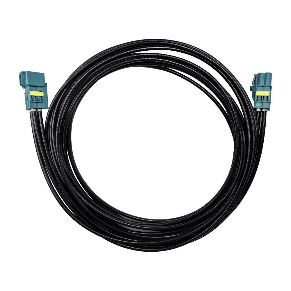
A coax cable carries radio-frequency signals and, in compatible systems, high-speed serialized data between antennas, cameras, control modules, and infotainment equipment. Its ability to maintain controlled impedance and protect signals from electromagnetic interference makes it well suited to modern vehicle electronics.
That does not mean any coaxial cable will work in an automotive system. A cable may have the right diameter but the wrong impedance. A connector may look correct but use a different mechanical code or cable interface. Even a properly matched assembly can lose too much signal if the cable run is long or the termination is poorly controlled.
Understanding the cable’s construction is the best place to start.
What Is a Coax Cable and How Is It Constructed?
The term “coaxial” comes from the cable’s two conductors sharing the same central axis. This geometry allows the cable to carry high-frequency signals while limiting interference from nearby motors, switching electronics, wireless systems, and power circuits.
A typical coax cable has four layers.
Center Conductor
The center conductor carries the signal. Depending on the cable design, it may be solid or stranded and made from copper, tinned copper, copper-clad steel, or another conductive material.
Solid conductors can provide stable high-frequency performance. Stranded conductors are usually more flexible, which can be useful when a harness must pass through tight spaces or withstand repeated movement. Neither option is automatically better—the right choice depends on frequency, routing, vibration, bend radius, and termination requirements.
Dielectric Insulation
The dielectric keeps the center conductor at a controlled distance from the shield. Its dimensions and material properties are critical because they help determine the cable’s characteristic impedance.
Here is where assembly quality matters. If the dielectric is crushed during crimping or damaged during stripping, the cable geometry changes at that point. The assembly may still pass a basic continuity test, yet show poor return loss or unstable high-frequency performance.
Outer Shield
The outer shield provides the signal return path and helps control electromagnetic interference. It may use foil, braided wire, or a combination of the two.
Shielding performance depends on more than coverage percentage. Braid construction, foil overlap, grounding, connector design, and termination quality all affect the final result. We often see otherwise suitable cables underperform because the shield was opened too far during preparation or terminated inconsistently at the connector.
Outer Jacket
The jacket protects the internal layers from abrasion, moisture, chemicals, and mechanical damage. In an automotive coax cable, the jacket should be selected for the actual installation environment, including temperature, flexibility, fluid exposure, and routing conditions.
Keep in mind that the jacket alone does not make an assembly waterproof. Sealing also depends on the connector housing, cable seal, rear protection, crimping process, and fully mated condition.
How Does a Coax Cable Carry a Signal?
The signal’s electromagnetic field is concentrated mainly between the center conductor and the outer shield. Because that geometry remains consistent along the cable, the signal sees a controlled electrical path.
Three characteristics deserve particular attention:
Impedance is the cable’s characteristic opposition to a high-frequency signal.
Attenuation is the amount of signal lost as it travels through the cable.
Shielding effectiveness describes the cable’s ability to limit electromagnetic interference.
In practice, these characteristics are connected. A tight bend can disturb the cable geometry. A long cable increases attenuation. A poorly terminated shield can reduce EMC performance. The connector, cable, crimp, adapter, PCB transition, and mating interface must therefore be treated as one transmission channel.
Common Problems With Coax Cable Assemblies
Impedance mismatch causes signal loss
Connecting a 75-ohm cable to a system designed for 50 ohms creates a discontinuity that can produce reflections and reduce signal margin. Confirm the impedance of the module, PCB interface, connector, and cable before approving the assembly.
The connector fits the cable but not the module
Two coaxial connectors can look almost identical while using different codes, genders, terminal dimensions, or PCB interfaces. Use controlled drawings and mating part numbers rather than trying to identify a production connector from photographs alone.
Cable loss becomes excessive at the required length
A cable that works well over 300 mm may not meet the same performance requirement over three meters. Check attenuation at the actual operating frequency and finished length, including losses from connectors, adapters, and PCB transitions.
Coaxial Cable Types: 50 Ohms vs. 75 Ohms
There are many coaxial cable types, from miniature flexible cables used inside compact modules to larger low-loss cables used for longer RF runs. Impedance is one of the first distinctions engineers need to make.
50-Ohm Coax Cable
A 50-ohm cable is commonly used for RF communication, antenna, test, and automotive applications. In vehicles, these applications may include:
GPS and GNSS antennas
AM/FM and satellite radio
LTE and 5G telematics
Wi-Fi and Bluetooth
V2X communication
Remote keyless entry
Compatible coaxial SerDes links
FAKRA uses a nominal 50-ohm automotive RF interface. ISO 20860-1 defines dimensional and electrical requirements for a 50-ohm RF connection system used in road vehicles.
The 50-ohm rating alone is not enough to establish compatibility. Frequency performance, attenuation, cable diameter, temperature range, shielding, and connector termination still need to match the project specification.
75-Ohm Coax Cable
A 75-ohm cable is widely used in television, broadcast video, cable distribution, and other systems designed around that impedance.
It should not be substituted directly into a 50-ohm automotive RF link simply because the cable dimensions are similar. The mismatch can increase reflections and reduce the power or data margin available at the receiver.
Is RG174 Suitable for Automotive Use?
RG174 is a familiar small-diameter, flexible 50-ohm cable type. Its size makes routing easier in confined spaces, but its attenuation is generally higher than that of larger low-loss cables.
Imagine replacing a short antenna lead with a much longer RG174 assembly. The connector may mate correctly and the system may initially appear functional, but the additional cable loss could reduce reception under weak-signal conditions. Check the exact cable construction, frequency, length, temperature rating, shielding, automotive requirements, and crimp compatibility before specifying it.
Common Coax Cable Connector Types
Different industries use different coaxial interfaces. Familiar examples include SMA, SMB, BNC, TNC, N-type, MCX, MMCX, and FAKRA.
SMA
SMA is a threaded RF interface commonly found in antennas, test equipment, communication devices, and industrial electronics. Its threaded coupling provides secure mating, but the standard interface does not offer the automotive coding and housing features associated with FAKRA.
SMB, MCX, and MMCX
These miniature interfaces are used where compact size and push-on mating are important. Their suitability depends on frequency, retention force, cable size, environmental exposure, and installation method.
BNC and TNC
BNC uses a bayonet coupling and is common in test, broadcast, and video equipment. TNC uses a threaded coupling where more secure retention is required. Both are useful in their intended markets, but they are generally less convenient for high-volume automotive assembly.
FAKRA Automotive Connectors
A FAKRA connector combines a coaxial interface with an automotive housing, mechanical coding, and locking features. The coding system helps prevent mismating when one vehicle module has several RF ports.
Common applications include:
GNSS and navigation antennas
Cellular and telematics modules
AM/FM and satellite radio
Wi-Fi, Bluetooth, and V2X antennas
Selected automotive camera systems
Infotainment and communication equipment
FAKRA is not a universal camera connector. Its suitability depends on the camera’s serializer/deserializer architecture, required frequency range, cable length, module interface, and complete channel specification.
Explore our FAKRA automotive connector products for cable-end, PCB-end, straight, right-angle, and customized connection requirements.
Automotive Coax Cable Applications
GNSS and Vehicle Antennas
GNSS antennas receive low-level satellite signals, so cable attenuation and termination quality can have a noticeable effect on positioning performance. A suitable 50-ohm cable and FAKRA assembly connects the antenna to the navigation, positioning, or telematics module.
Longer cable runs require closer attention. The correct approach is to review the complete RF link budget at the required frequencies, not simply choose the smallest cable that fits the harness route.
Cellular, Wi-Fi, and V2X
Connected vehicles may have separate antennas for LTE, 5G, Wi-Fi, Bluetooth, satellite services, and V2X. FAKRA coding helps production workers and service technicians distinguish these connections.
For conversions or aftermarket installations, a properly specified FAKRA antenna adapter can connect different interfaces. The adapter must still match the system’s impedance, connector gender, code, and frequency requirements.
ADAS Cameras
Some ADAS cameras use coaxial SerDes links to carry video and control data. Certain architectures can also supply power over the same coaxial connection.
These links place tighter demands on controlled impedance, insertion loss, shield continuity, crimping, and PCB transitions. Before selecting FAKRA for a camera, confirm the camera, ECU, SerDes, cable, and channel requirements.
Infotainment and Radio
Coaxial cables connect broadcast and satellite-radio antennas to vehicle receivers. They may also support navigation and other infotainment functions where stable RF performance is required.
In vehicles with several antenna feeds, mechanical coding reduces the risk of connecting a radio input to a GNSS, cellular, or another incompatible port.
How to Select the Right Coax Cable and Connector
Start with the electrical and mechanical requirements, not the connector’s appearance.
1. Confirm the signal and impedance
Identify whether the link carries an antenna signal, analog RF, or compatible serialized data. Then confirm the impedance required by the module and mating interface.
2. Define the frequency range and loss budget
Specify the operating frequency and maximum acceptable insertion loss. Attenuation should be checked at the finished cable length and actual operating frequency.
3. Choose the cable construction
Consider diameter, flexibility, shielding, bend radius, jacket material, temperature, abrasion, and chemical exposure. A smaller cable can simplify routing, but the tradeoff may be higher attenuation or reduced mechanical strength.
4. Confirm both connector interfaces
Define the connectors at both ends, including code, color, plug or jack configuration, cable exit direction, and mating part number. A drawing is far more useful than a product photograph.
5. Describe the installation environment
State whether the assembly will be installed in the cabin, roof, bumper, engine compartment, or another exposed area. If sealing is required, specify the expected ingress test and operating conditions.
6. Agree on manufacturing and testing
Depending on the project, production controls may include cable stripping, shield preparation, contact crimping, housing assembly, continuity testing, pull-force inspection, insertion-loss measurement, and VSWR testing.
We provide custom coaxial cable assemblies and OEM/ODM services based on customer drawings, mating interfaces, cable specifications, finished length, application, and quantity. Our team can review the requirements before preparing samples or a production quotation.
Frequently Asked Questions
Is FAKRA a coaxial connector?
Yes. FAKRA is an automotive connector system based on a nominal 50-ohm coaxial interface. The correct code, housing, cable, orientation, and electrical performance must be selected for each application.
Are all FAKRA cable assemblies waterproof?
No. Both sealed and unsealed configurations exist, and sealing performance depends on the complete mated assembly. Include the installation location and required ingress test when requesting a custom cable.
Can you customize cable length and connector configuration?
Yes. We provide custom cable lengths, FAKRA codes, connector orientations, and end configurations through our OEM/ODM service. Send us the mating interfaces, drawing, cable requirements, and expected quantity for review.
What information do you need for a quotation?
Provide the connectors at both ends, FAKRA code, cable type, finished length, frequency range, environmental requirements, sample quantity, annual volume, and available drawings. These details help us check compatibility and quote the correct construction.
Conclusion
A coax cable is not just a shielded wire. Its impedance, attenuation, shielding, frequency performance, connectors, and assembly process determine how reliably it carries a signal in the vehicle.
For automotive RF and compatible coaxial data applications, FAKRA adds coding and locking features that simplify vehicle integration. The best results come from evaluating the cable, connector, PCB interface, mating module, installation environment, and validation requirements as one system.
Need a custom automotive coax cable or FAKRA cable assembly? Send us your mating interfaces, cable type, length, frequency range, environmental requirements, drawing, and estimated quantity.
Contact us to request samples, OEM/ODM engineering support, or a custom quotation.