How to Build an RF Budget for FAKRA Connector Insertion Loss in GNSS, 5G, and Telematics Systems

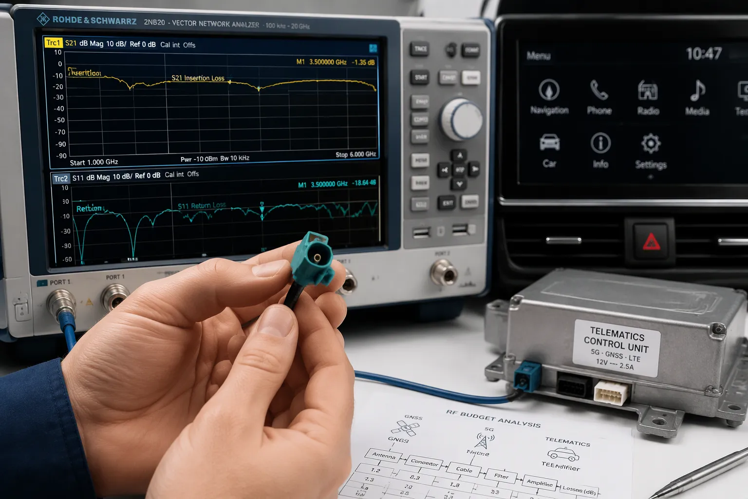
You are designing a GNSS or 5G antenna link. The RF connectors and cable assembly must leave enough RF margin. Define requirements, select RF connectors by frequency and environment, calculate attenuation with derating, allocate margin, then validate by test.
FAKRA Connector Insertion Loss matters because weak margin degrades reception. This interface dominates automotive and telematics links, so the penalty compounds across every mating. Performance depends on connector design, cable type, length, connection count, assembly quality, routing, and the full RF system. Choose RF connectors carefully.
In Short: Build your RF budget from requirements first, always derate manufacturer data, count every mating, confirm the exact frequency band and test conditions, and then validate the finished assembly with measurement.
Key Takeaways
Define your system requirements first. Know if the path is receive-only, transmit-only, or bidirectional.
Always derate manufacturer data. Account for temperature, aging, and mating wear to keep margin.
Count every connection in the RF path. Each FAKRA mating pair and adapter adds loss.
Validate your finished assembly with a VNA test. Measure at your actual frequency band.
Choose the right FAKRA assembly for your needs. Standard assemblies save cost; custom ones offer flexibility.
What Is FAKRA Connector Insertion Loss?
Insertion loss is the reduction in signal power caused by a component placed in an RF path. That component can be a connector, a cable, an adapter, a transition, or a full assembly. Engineers express it in decibels (dB). A higher number means more signal loss. You will not find one universal insertion-loss value for all FAKRA connectors. Each part, cable, and assembly behaves differently.
Loss Sources in a FAKRA Interface
Many factors shape the insertion loss of a FAKRA interface. Treat each one as an input to your budget, not an afterthought.
Loss source | What it does to your RF path |
|---|---|
Operating frequency | Loss typically rises as frequency climbs, so test at your real band |
Connector design | Contact geometry and dielectric materials set the baseline |
Cable construction | Conductor, dielectric, and shield quality drive attenuation |
Longer runs add more signal loss | |
Number of connectors | Every mating pair adds its own contribution |
Each adapter introduces another loss point | |
Termination quality | Poor crimps or solder joints raise loss and reflections |
Assembly quality | Workmanship decides whether the design performs as specified |
Mechanical stress | Bending and pulling can shift performance over time |
Temperature and environment | Heat, vibration, and moisture affect long-term behavior |
You should evaluate the connector together with the cable and the mating interface. A perfect connector on a poor cable still delivers a poor link.
Component Loss vs. Total Link Loss
Component loss describes one part in isolation. Total link loss describes the whole chain from transmitter or antenna to receiver. Your budget must use the second number. Add the cable, every FAKRA mating pair, each adapter, and the module interface. Then compare the sum against your available margin.
Do not confuse insertion loss with related RF terms. Insertion loss measures power lost through a component. Return loss measures reflected power caused by a mismatch. VSWR is another way to express that mismatch. Impedance matching keeps reflections low across the frequency range. A part can show good return loss and still add meaningful insertion loss, so check both.
LEADSIGN FAKRA RF connectors use a 50 Ω impedance and cover DC up to 6 GHz. They specify return loss ≥ 18 dB. These figures describe the connector family, not your finished cable assembly. Final RF performance must be confirmed for the exact assembly, cable, and test conditions. Ask for measured data at your operating frequency before you lock the budget. That step protects your margin and your automotive program schedule.
GNSS, 5G, and Telematics Application Considerations
Frequency Bands and Link Sensitivity
Each application lives in its own part of the spectrum. GNSS reception sits in the L-band, and L1/L5 band reception covers two common satellite signals. LTE, 4G/5G telematics, sub-6 GHz and mmWave bands, Wi-Fi, and satellite radio each need their own review. Insertion loss is frequency-dependent, so evaluate it at the intended frequency. FAKRA connectors, FAKRA cable assemblies, and the full RF chain all shift with frequency. Confirm the required frequency range and test conditions before you commit.
Receiver and transmitter paths carry different weight. A receive-only chain depends on sensitivity, so every decibel of attenuation in the GNSS/GPS antenna feeds eats margin. A transmit path depends on output power and regulatory limits. A bidirectional link needs both checks. RF connectors on the receive side carry more weight than RF connectors on the transmit side. The formula changes with the architecture, so state the path type first.
Environment, Coding, and Compliance
Temperature extremes, vibration, humidity, and ingress protection all act as derating inputs. Automotive qualification and EMC expectations belong in the RF budget too. FAKRA interfaces and RF adapters add their own attenuation. Ask for evidence rather than assuming it.
FAKRA coding and keying prevent mismating and installation errors. Housing, coding, gender, mating interface, and cable exit direction all matter. Correct FAKRA coding does not prove RF performance, though. Confirm electrical specs separately.
Many automotive RF systems use a 50 Ω impedance design. Confirm the actual system specification, because not every vehicle system or FAKRA product shares identical impedance behavior. Select FAKRA connectors, FAKRA cables, and FAKRA assemblies as one chain. Automotive GPS antennas and GNSS antennas deserve the same scrutiny as the module side. Match every RF interface and every RF connector pair, then verify the whole path. Document the frequency range for each FAKRA part and each RF connector, then recheck the frequency range when the band changes.
Building the RF Link Budget Step by Step

Define Requirements and Gather Data
Start with the system architecture. Decide whether the path is receive-only, transmit-only, or bidirectional. Then write down the required receiver margin and the transmitter output level. Add antenna gain where it applies. Collect manufacturer data for every RF component in the chain. That data includes fakra connector insertion loss, cable attenuation per unit length, and adapter performance. Ask for measured values at your actual frequency range, not a generic curve.
You can express the general relationship in plain terms. Available signal margin equals the transmitter or antenna output level, plus antenna gain where applicable, minus cable loss, minus connector loss, minus adapter loss, minus other system losses, minus the required receiver margin. The exact formula depends on your system architecture. A receive-only gnss path and a bidirectional 5g telematics link will not share the same equation.
The table below is illustrative only. It does not represent LEADSIGN product specifications.
RF path component | Possible effect | What you should confirm |
|---|---|---|
Antenna | Gain or loss at the band | Pattern and gain at your frequency |
FAKRA connector | Adds insertion loss per mating | Measured data for the exact part |
Coaxial cable | Attenuation rises with length | Cable type and attenuation curve |
Cable length | Longer routes add more loss | Actual routed length plus slack |
Adapter | Each transition adds loss | Whether the adapter is necessary |
Additional connector pair | Compounds total loss | Every mating counted |
Module interface | Input and output requirements | Module datasheet limits |
Environmental factors | Derating over life | Temperature and vibration range |
Receiver or transmitter requirement | Sets the margin floor | Sensitivity or output spec |
Calculate, Allocate, and Derate Margins
Cable length drives total loss in ways that surprise new designers. Longer routes, extra slack, cable type, conductor and dielectric design, shielding, bend radius, compression, routing near heat or interference, and connector stress all matter. Do not rely on universal dB-per-meter values. Use the attenuation curve for your specific cable and confirm it at your frequency.
Total loss also climbs with multiple fakra connectors, adapters, extension cables, transitions, inline couplers, and multi-branch assemblies. Count every connection in the RF path. Reduce unnecessary transitions where you can. Keep the installation practical at the same time. A route that is easy to service often beats a theoretically shorter one.
Now allocate margin. Reserve headroom for temperature extremes, aging, and mating-cycle wear. A low insertion loss at room temperature does not guarantee the same result after years of automotive service. Subtract these allowances from your calculated margin. Confirm the residual margin still meets performance and regulatory needs. If it does not, revisit the cable type, the connector count, or the frequency range. Build your signal loss budget once, then update it whenever a component or band changes. That discipline keeps your rf path predictable from prototype to production.
Trade-Offs: Standard vs. Custom FAKRA Assemblies
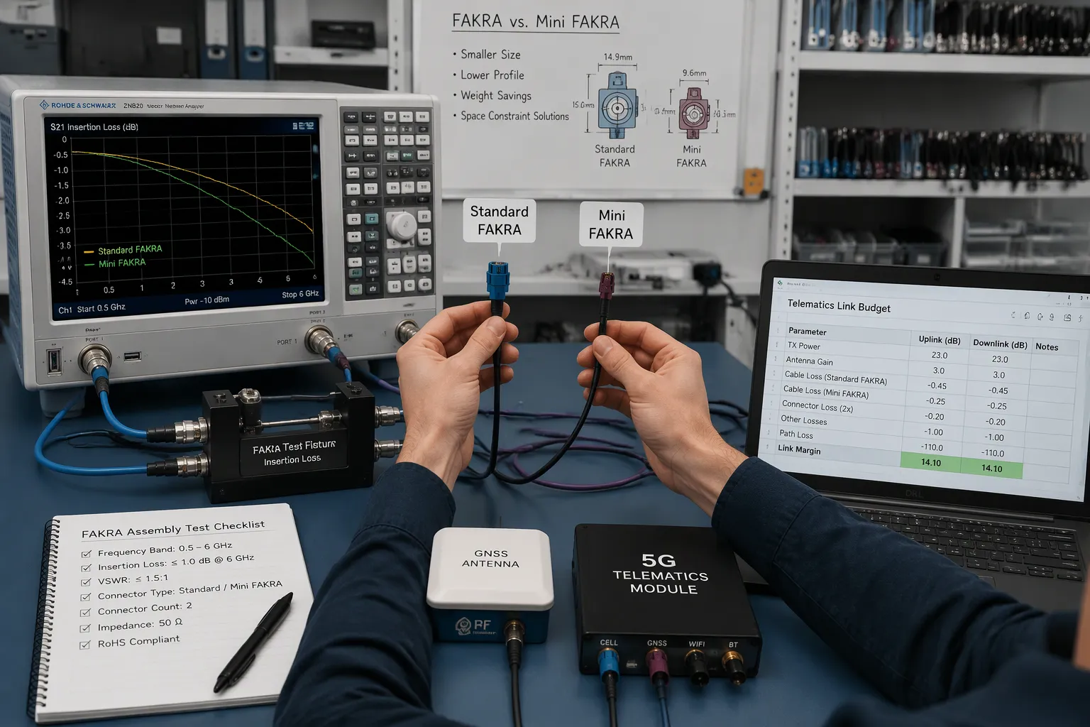
A standard fakra cable assembly fits best when the antenna and module interfaces are known, the length is fixed, the routing is standard, and you buy the same configuration repeatedly. A custom assembly is preferable for special lengths, multiple connectors, mixed configurations, straight-to-right-angle designs, limited space, special coding, prototype development, OEM integration, and low-volume programs. Both options serve real needs. Match the choice to your program stage and volume.
Performance, Cost, and Mini FAKRA Connectors
Mini fakra connectors shrink the package. They also change your coding options and your usable frequency range, so treat size, coding, frequency range, and insertion loss as selection criteria. Compare mini fakra connectors against standard fakra parts on all four points before you commit. LEADSIGN offers both FAKRA and Mini FAKRA solutions for evaluation. Ask for measured data at your band rather than assuming a value.
Cost follows complexity. A standard assembly usually wins on unit price and lead time. A custom assembly buys routing freedom and interface matching at higher tooling and setup effort. Weigh that trade-off against your 5g or GNSS margin, not against price alone.
Testing and Verification Methods
Validate every assumption in your budget. Measure insertion loss with a vector network analyzer (VNA) across your frequency range. Run temperature cycling and mating-cycle testing against the same conditions you budgeted. Then feed the results back into the budget. If measured loss exceeds your allowance, adjust the cable type, the connector count, or the routing before release.
Use this checklist to align RF and procurement.
Specification | Why it matters | Information to confirm |
|---|---|---|
RF application | Sets the path type | Receive, transmit, or both |
Frequency band | Loss varies with frequency | Exact band and test conditions |
Antenna type | Drives gain and match | Interface and connector gender |
Module type | Sets input limits | Datasheet requirements |
Cable type | Drives attenuation | Attenuation curve at your band |
Cable length | Longer runs add loss | Routed length plus slack |
Number of connectors | Each mating adds loss | Count every pair |
Connector family | Sets size and coding | FAKRA or Mini FAKRA |
Connector gender | Must mate correctly | Jack or plug |
Connector coding | Prevents mismating | Color and key code |
Adapter requirements | Each adapter adds loss | Whether it is needed |
Impedance | Must match the system | 50 Ω confirmation |
Shielding | Controls interference | Shield type and coverage |
Cable routing | Affects stress and loss | Path near heat or noise |
Bend radius | Protects performance | Minimum radius |
Operating environment | Drives derating | Temperature and moisture |
Required samples | Proves the design | Quantity and timing |
Test conditions | Makes data comparable | Frequency and setup |
Technical drawings | Locks the configuration | Approval before build |
Order quantity | Sets pricing tier | Annual and first order |
Delivery requirements | Protects the schedule | Lead time and milestones |
Avoid these common mistakes. Do not look only at the connector and ignore the cable. Do not assume all fakra assemblies share the same fakra connector insertion loss. Do not ignore operating frequency. Do not use an unnecessarily long cable or add too many adapters. Count every rf connector in the path. Check return loss and impedance matching, not just attenuation. Never select a cable by appearance, ignore coding, bend or crush the cable, or apply mechanical force to the connector. Do not compare tests made under different conditions. Do not treat an illustrative budget as a product specification. Request samples and drawings early.
Low insertion loss alone does not guarantee system reliability. Judge rf performance together with mechanical and environmental reliability.
You now have a repeatable workflow. Define requirements first. Calculate loss from data, then derate it. Allocate margin with discipline. Validate the finished assembly by test. Budget every mating, derate for the automotive environment, and confirm the exact frequency range and test conditions. Revisit the budget when components or bands change.
LEADSIGN supplies fakra connectors, fakra coaxial cables, fakra cable assemblies, fakra extension cables, custom fakra cable assemblies, Mini FAKRA connectors, and automotive antenna cable solutions. Share your application, frequency band, antenna and module interface, connector type and coding, cable length, connector count, routing, environment, quantity, and sample or drawing needs. Email info@leadsignauto.com for rf connectors, rf cable configuration, custom lengths, drawings, samples, or a quotation. Confirm final rf performance for your exact assembly and test conditions.
FAQ
How do I estimate fakra connector insertion loss before I have samples?
Start with manufacturer data at your actual frequency. Add cable attenuation for your routed length. Count every fakra mating pair and adapter. Then derate for temperature and aging. Treat the result as an estimate, not a guarantee. Confirm it with a VNA measurement on the finished assembly.
Does a longer cable always mean more rf loss?
Yes, attenuation rises with length for any given cable. But cable type matters just as much. A short run of a lossy cable can beat a long run of a good one. Compare attenuation curves at your band. Then choose the shortest practical route that still allows service access.
Why should I test rf connectors at my real frequency?
Loss changes with frequency, so a value measured at one band tells you little about another. Ask for data across your required frequency range. Confirm the test setup matches your assembly. This step keeps your rf budget honest and protects your receiver margin.
How many fakra matings should I count in one vehicle link?
Count every one. That includes the antenna side, the module side, any inline coupler, and each extension cable joint. Each fakra pair adds its own loss. Fewer transitions usually mean less total loss. Keep the count visible in your rf budget document.
Can LEADSIGN help me configure an automotive fakra assembly?
Yes. LEADSIGN supplies fakra connectors, fakra coaxial cables, fakra cable assemblies, and Mini FAKRA options. Share your application, frequency band, interfaces, coding, cable length, connector count, routing, and environment. The team can support rf cable configuration, drawings, samples, and quotations. Email info@leadsignauto.com to start.
See Also
Why GPS Antennas Equipped with Fakra Connectors Matter So Much
The Critical Role of GPS Fakra Antennas in Modern Navigation Systems
Why Fakra Antennas Are Essential for Vehicle Communication Systems Today