HSD Z Code Cable Length Guide for Video Applications

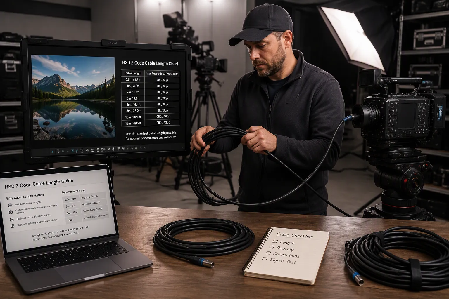
You extend a rear-view camera cable or LVDS display link. The image turns unstable, delayed, noisy, or disappears. The cable length and routing path were never validated. This problem appears often with high-speed video links. An HSD Z code cable carries 100-ohm differential signals for automotive video systems. No universal fixed maximum length exists for these cables. The correct length depends on protocol, data rate, cable construction, shielding, routing, connector transitions, and validation. This guide covers technical basics, application-specific risks, a selection checklist, and a risk table.
Key Takeaways
No fixed maximum length works for every HSD Z code cable. The right length depends on your specific setup.
Longer cables weaken video signals and cause noise, delay, or blank screens. Keep cables short and shielded.
Always test your exact cable path with a sample or test report. This prevents failures in your video system.
Check connector code, gender, and impedance before you order. A mechanical fit does not guarantee good performance.
Route cables away from power wires and sharp bends. Use locking connectors and avoid splices to maintain signal quality.
Why HSD Cable Length Matters in Automotive Video
Signal Integrity Risks in Vehicle Video Links
You run a high-speed differential link through a vehicle. The cable length grows. Several problems appear at the same time. Insertion loss rises across the operating range. This loss weakens the high-frequency content of your video signal. Skew between the positive and negative conductors also increases. That skew distorts the differential waveform. Noise susceptibility grows as the link becomes longer. Nearby power wires, motors, and infotainment electronics couple energy into the cable. The shield must stay continuous to block this interference.
An HSD cable carries 100-ohm differential signals for automotive video. The nominal impedance must stay stable along the entire path. Sharp bends, excessive untwisting of cable pairs, or poor shield termination reduce channel performance. A cable assembly that mates mechanically can still be electrically incompatible. You must evaluate the complete link budget, not just continuity. Impedance, insertion loss, return loss, skew, EMI, and power-voltage drop all matter for high-speed video links.
Real-World Symptoms of Length-Related Failures
You will notice specific symptoms when cable length and routing are not validated. The image may become unstable. It may flicker or drop frames. A delay can appear between the camera feed and the display. Noise, streaks, or color artifacts may show on the screen. In severe cases, the display shows no signal at all.
These symptoms do not always mean the cable is too long. They mean the signal margin has dropped below what the system needs. As HSD cable length increases, insertion loss rises. This degrades high-frequency automotive video signals such as GMSL2 or FPD-Link III. To maintain a stable data link over long vehicle chassis runs, you need high-grade shielded cables with tightly controlled 100-ohm impedance and optimized PCB-side equalization. A rear-view camera link may work at one length and fail at another. The difference often comes down to routing, connector transitions, and termination quality.
HSD Z Code Cable and 100-Ohm Differential Basics
What Is an HSD Z Code Cable?
HSD stands for High-Speed Data. An HSD connector system carries 100-ohm differential signals for automotive video and data links. You will find these connectors in LVDS displays, rear-view cameras, USB, Ethernet, and infotainment systems. The HSD Z code cable uses a neutral coding option. This code works as a universal choice across many applications. However, you must confirm compatibility by drawing, sample, photo, or part number before you order. Do not assume that a code Z interface mates with every HSD port.
You should not confuse HSD connectors with standard FAKRA, HSD 50-ohm RF connectors. FAKRA cable assemblies use 50-ohm coaxial interfaces for antennas and GNSS. HSD uses four inner contacts for differential pairs. A standard FAKRA, HSD system and a 100-ohm differential system serve different purposes. Check the interface type before you select any cable. You can explore the HSD cable assembly category for available options.
100-Ohm Differential Signal and Shielding
A 100-ohm differential link depends on controlled impedance along the entire path. Conductor geometry, pair balance, contact position, and exposed conductor length all affect performance. The shield transition at the connector matters too. A cable assembly may pass a basic continuity test while still producing errors at the required data rate. You need to evaluate differential impedance, crosstalk, and protocol margin when the link specification requires them.
HSD connectors work as part of a fully shielded system. They pair with shielded, twisted quad cables. This combination preserves signal integrity and blocks interference from crosstalk or external sources. Shielding continuity must stay intact from end to end. Any break in the shield path reduces noise immunity. For reliable automotive video, keep impedance stable and maintain shielding across every connector transition.
LVDS Displays, Rear-View Cameras, and Infotainment Links
LVDS Video Cable Applications
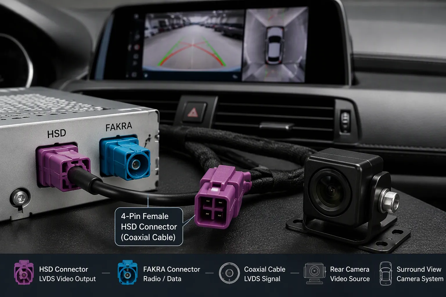
Automotive display systems rely on HSD connectors for high-speed links. These connectors support LVDS rear-view links, infotainment screens, USB, Ethernet, and APIX connections. A typical part is the FAKRA LVDS assembly with Dacar 535 wire. It uses 4-pin female HSD terminals (Rosenberger D4K10A-1D5A5-Y, C code) on both ends. HSD cables of this grade carry LVDS data for BMW Combox entertainment, rear-view displays, and in-vehicle dashboards. Audi and VW use similar designs. High-performance 4-pin female plugs deliver stable, fast data transmission. Their shielding blocks interference and meets strict in-vehicle stability needs.
For dependable display links, keep differential impedance stable, shielding consistent, and skew low. Review the HSD LVDS cable category for display options. Browse the FAKRA HSD cable category for mixed coax and differential paths. Confirm each choice with a drawing or sample before ordering.
Rear-View Camera and Infotainment Links
In a reversing system, the camera video travels through a FAKRA cable assembly to the central screen. The sensor module links to a central control unit, surround-view controller, or ADAS ECU. This automotive camera connector path carries HD content for delay-free display. A 360-degree surround view system uses four to six sensors with FAKRA cabling for seamless image stitching. As HD demand grows toward 1080p, 4K, and HDR, some vehicles adopt FPD-Link III or GMSL. FAKRA appears in these shielded links. These links must carry high-resolution real-time video streams without artifacts.
FAKRA connectors are built for single-ended RF transmission over coaxial lines, whereas high-speed differential links handle digital data over shielded twisted quad lines. The two are not interchangeable.
FAKRA cable assemblies use single-core 50-ohm coaxial construction with standard EMI immunity and a smaller footprint. Their typical use includes power over coax to remote sensors. A FAKRA cable assembly often suits these paths. Shielded quad assemblies use a four-pin, 100-ohm twisted pair construction with superior EMI immunity for noisy environments. Check whether your path is single-ended or differential. An hsd-based automotive camera connector belongs in high-EMI zones. For simpler rear-view runs, a different automotive camera connector pairs with a standard FAKRA, HSD interface.
What Happens When an HSD Video Cable Is Too Long?
Insertion Loss, Skew, and Noise
A longer cable does not automatically fail. The signal margin shrinks when the cable and system are not designed to work together. Insertion loss rises as length increases. This loss weakens the high-frequency content that carries your video data. The receiver must work harder to distinguish ones from zeros. At some point, the receiver cannot recover the signal.
Skew creates a second problem. Skew measures the timing difference between the positive and negative conductors in a differential pair. A longer cable amplifies any imbalance between these two lines. The differential waveform distorts. Your display may show color shifts, ghosting, or unstable images. Noise susceptibility also grows with length. The cable acts like an antenna. It picks up interference from motors, power wires, and infotainment electronics. A continuous shield blocks much of this noise. Any break in the shield path lets interference reach the signal conductors.
These three effects work together. Insertion loss weakens the signal. Skew distorts its shape. Noise adds unwanted energy. The receiver sees a degraded waveform. It may still decode the data at first. As conditions change, the link becomes unreliable. Temperature shifts, vibration, and aging all reduce margin further.
Signal Margin and System Failure
Signal margin describes the difference between the actual signal quality and the minimum level the receiver needs. A short cable with good shielding provides large margin. A long cable with poor routing consumes that margin. When margin reaches zero, the link fails. You see a blank screen, frozen frames, or intermittent dropouts.
You cannot predict failure from length alone. The data rate matters. A higher data rate demands more bandwidth and tighter timing. The cable construction matters. A well-shielded twisted quad cable preserves signal integrity better than a generic cable. The routing path matters. Sharp bends, tight bundles, and parallel runs with power wires all reduce margin. Connector transitions add loss and reflection at every junction.
Do not trust claims about a fixed maximum length for an HSD video cable. Do not accept guaranteed camera resolution or data rate without a part-specific test report. Every automotive video link is different. The camera model, display model, head unit, and protocol all affect performance. Validate your specific configuration with a drawing, sample, or test data. That approach protects your project from unexpected failures.
Cable Length, Shielding, Skew, and Routing Path
Cable length alone does not determine success. Construction, shielding, termination quality, routing, bend radius, connector transition, and data protocol all affect signal integrity. You cannot separate length from these variables. The whole path decides whether an automotive link works.
Cable Construction and Bend Radius
Choose foil plus braid double shielding. This blocks interference from motors and power wires. Use twisted quad conductors to cancel common-mode noise. Keep differential impedance at 100 ohms.
Respect the minimum bend radius. Tight bends change conductor spacing and cause reflections. Avoid flexing near termination points. Doors, liftgates, and steering-column-adjacent areas move repeatedly. Flexing can break shield continuity.
Keep distance from power cables. Cross at 90 degrees if unavoidable. Place a zip-tie near each connector. Never splice the run. A splice ruins impedance.
Connector Transitions and Routing Path
Every connector transition adds a small impedance discontinuity. Keep the number low. Check that connectors seat fully. A poor mate raises insertion loss and noise. Use an HSD assembly with locking connectors.
Routing determines field durability. Keep the link away from sharp edges and hot surfaces. High-risk zones include tailgate hinges, front bumpers, and cockpit display areas. Tailgate hinges flex repeatedly. In automotive video systems, routing often decides whether an assembly works.
Cable Situation | Possible Signal Risk | What to Check | Buyer Recommendation |
|---|---|---|---|
Short dashboard display link | Crosstalk from nearby modules | Separation from power sources | Shielded HSD assembly |
Medium head-unit to display link | Skew and insertion loss | Twisted quad geometry and bend radius | Request drawing or sample |
Noise near tailgate hinge | Flex zones and shield continuity | Locking connector | |
Long rear-to-front vehicle routing | High insertion loss and EMI | Route away from high-voltage cables | Validate with test report |
Multi-connector or adapter path | Reflection at each transition | Count junctions and check seating | Reduce transitions |
Validate the path with a sample. Test your actual vehicle-length runs.
Why There Is No Universal Maximum HSD Cable Length
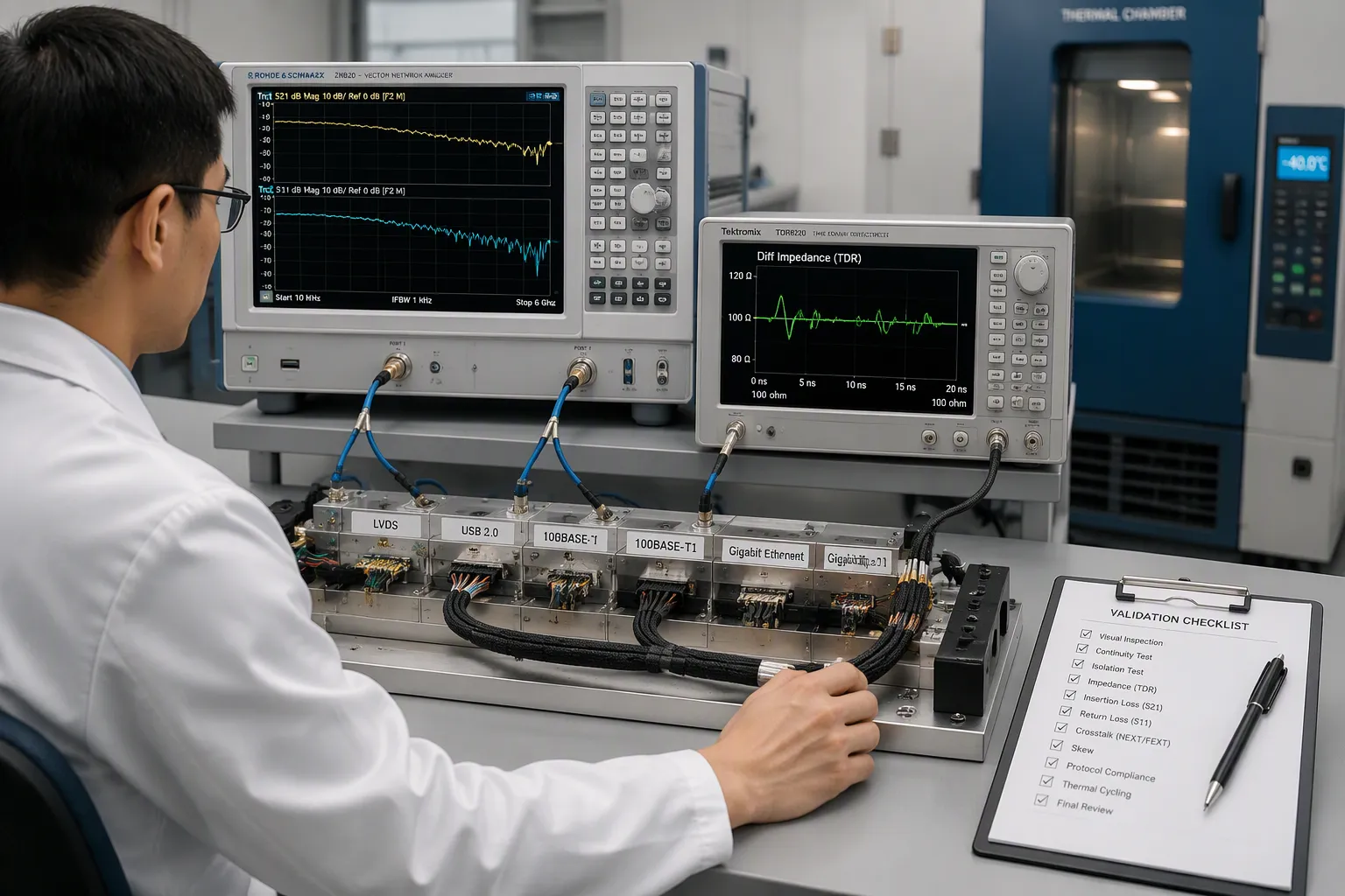
You cannot point to one number and say every HSD link works up to that distance. The correct cable length depends on the protocol, data rate, cable construction, shielding, routing path, connector transition, and validation requirements. Each factor changes the signal margin. A length that works for one system may fail for another.
Data Rate, Cable Type and Connector Requirements
The data rate, cable type and connector requirements set the foundation for any length decision. Different protocols tolerate different distances. These differences show why no single maximum applies across all systems.
The data rate, cable type and connector requirements also shape which tests you need. A TDR test verifies differential impedance stays within 100 ohms plus or minus 10 percent across the connector, cable body, termination, and PCB transition. A VNA measures insertion loss (S21) and return loss (S11). Skew must stay tightly controlled for HSD harnesses. Exceeding the limit causes inter-symbol interference. Shielding effectiveness and post-environmental re-tests after thermal cycling and vibration complete the picture.
Protocol and Validation Dependencies
Your protocol choice drives the validation plan. LVDS video links connect a camera to an ECU or an ECU to a display. USB 2.0 handles infotainment and phone integration. A 100BASE-T1 link supports domain controller communication and diagnostics. APIX serves automotive SerDes video. Each protocol stresses different signal integrity parameters.
The Rosenberger HSD Z-code male-to-female design and LEONI Dacar 535 cable can be used in compatible LVDS, APIX, FPD-Link, GMSL, USB and Ethernet links for HD video, touch-control commands and device communication. Its compact 20cm length suits installation inside head units and display-control enclosures while minimizing excess cable.
Do not claim universal compatibility unless you verify it by camera model, display model, head unit model, mating connector, drawing, or sample. A connector that mates mechanically may still fail electrically. Validate your specific configuration before you commit to production.
HSD Z Code Cable Length Selection Checklist
Cable Compatibility and Connector Requirements
You must confirm several parameters before you order an HSD Z code cable. Start with the HSD code letter. The code letter (A, B, C, or Z) prevents mismating with other codes. Code Z works as a neutral fit across many sockets. This makes code Z useful for diagnostics and aftermarket work. However, code Z lacks the specific error-proofing that factory assembly lines need. Mechanical keying on standard codes stops wrong connections during fast production. You should verify the complete connector part number, gender, and mating interface. Do not select based only on connector color codes or product photos. Different keying arrangements create different mechanical mating relationships. Cable compatibility depends on more than a visual match.
Check connector gender next. Confirm plug or jack, male or female. The head unit side often uses a jack. Orientation matters too. A straight or right-angle cable exit must fit your routing space. Right-angle exits help in tight bends behind the dash. You also need to specify 100-ohm differential impedance, shielding type, and skew control. These electrical parameters keep your signal eye open. Poor termination quality creates impedance discontinuities. Always evaluate the complete link budget, not just cable loss alone.
Application and Routing Details
Your application shapes every choice. State whether you need an LVDS display link, a rear-view camera path, or an infotainment connection. Provide the protocol or data rate if you know it. LVDS, APIX, USB, and Ethernet each use different pinouts. Give the camera model, display model, and head unit model. These details confirm the mating interface. An automotive camera connector must match the module port exactly.
Describe your routing path. Include the bend radius limitation and the number of connector transitions. Every transition adds reflection and loss. Keep the count low. Supply a drawing, sample photo, or part number. State your quantity and any testing requirement, such as TDR or continuity checks. This information lets suppliers validate performance after temperature, vibration, and bending exposure. For automotive projects, include vehicle-level EMC testing, not only component tests. Contact us with your drawings and project details for HSD Z code cable support.
Frequently Asked Questions
HSD Cable Length and Video Quality
Does HSD cable length affect automotive video quality?
Yes, length affects signal quality. Longer runs increase insertion loss and skew. The video signal weakens and distorts. Noise from motors and power wires also grows. You may see flickering, delay, or a blank screen. Keep the cable short and shielded. Validate your specific path with a sample before production.
Can an HSD cable be used for rear-view cameras and LVDS displays?
Yes, HSD connectors serve both applications. They carry 100-ohm differential signals for camera video and LVDS display links. You must confirm the mating interface by drawing or sample. Check the connector code, gender, and orientation. A mechanical fit does not guarantee electrical performance. Always verify the complete link.
Maximum Length and Custom Ordering
What is the maximum length for an HSD Z code video cable?
No universal maximum exists. The correct length depends on protocol, data rate, cable construction, shielding, and routing. A short dashboard link and a long rear-to-front run behave differently. Do not trust a single fixed number. Validate your automotive link with a part-specific test report or sample.
What information is needed to order a custom HSD video cable?
Provide the HSD code, connector gender, and straight or right-angle orientation. State the cable length, impedance, and shielding needs. Give the camera, display, and head unit models. Describe the routing path and bend radius limits. Include keying details, quantity, and any testing requirement. Send a drawing or sample photo for confirmation.
No universal fixed maximum length exists for an HSD Z code cable in automotive video applications. You must validate cable length, routing, and connector transitions with drawings, samples, or part-specific test reports. Before you order, check the HSD code, connector gender, impedance, shielding, and application requirements. These details protect your video link from failure.
Contact LEADSIGN with your drawings, samples, connector photos, camera models, display models, head unit models, routing requirements, or video project details. The team supports HSD Z code cable and custom HSD video cable projects. Send your specifications through the contact page to start your automotive video cable validation.
FAQ
Does HSD cable length affect automotive video quality?
Yes. Longer runs raise insertion loss and skew. The video signal weakens and distorts. Noise from motors and power wires also grows. You may see flickering, delay, or a blank screen. Keep the cable short and shielded. Validate your specific path with a sample before production.
What is the maximum length for an HSD Z code video cable?
No universal maximum exists. The correct length depends on protocol, data rate, cable construction, shielding, and routing. A short dashboard link and a long rear-to-front run behave differently. Do not trust a single fixed number. Validate your automotive link with a part-specific test report or sample.
Can an HSD cable be used for rear-view cameras and LVDS displays?
Yes. HSD connectors serve both applications. They carry 100-ohm differential signals for camera video and LVDS display links. You must confirm the mating interface by drawing or sample. Check the connector code, gender, and orientation. A mechanical fit does not guarantee electrical performance. Always verify the complete link.
What information is needed to order a custom HSD video cable?
Provide the HSD code, connector gender, and straight or right-angle orientation. State the cable length, impedance, and shielding needs. Give the camera, display, and head unit models. Describe the routing path and bend radius limits. Include keying details, quantity, and any testing requirement. Send a drawing or sample photo for confirmation.
See Also
Why HSD Cable Assembly Plays a Crucial Role in Modern Technology
How HSD LVDS Cables Improve Connectivity in Various Applications
Unlocking Infotainment Potential: The Power of HSD to USB Cables
Why LVDS/GVIF Cable Is Essential for Vehicle Information Systems
Boosting Vehicle Performance Through the Use of HSD to USB 2.0 Cables