FAKRA and HSD Connectors for Autonomous Driving Systems: Applications and Selection Guide

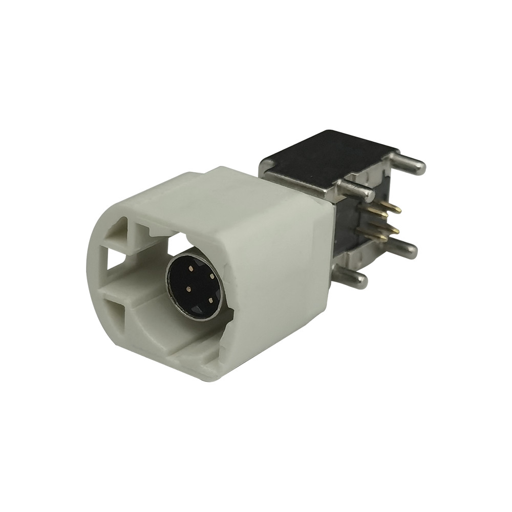
Modern ADAS and autonomous vehicles depend on cameras, antennas, displays, positioning modules, communication units, sensors, and centralized computing platforms. FAKRA and HSD connectors for autonomous driving systems perform different but complementary functions within this electronic architecture. FAKRA primarily carries automotive RF and coaxial signals, while HSD is designed for shielded high-speed differential data connections.
An incorrect connector or cable assembly can cause excessive signal loss, unstable video, electromagnetic interference, reduced positioning accuracy, or intermittent system failure. Selecting an interface therefore involves more than finding a mechanically compatible housing. Engineers must consider signal type, impedance, protocol, operating frequency, cable construction, shielding, installation space, environmental exposure, and validation requirements.
This guide explains where FAKRA and HSD are commonly used, how they differ, and what engineering and purchasing teams should specify when sourcing autonomous vehicle connectors and custom cable assemblies.
Why ADAS Requires Specialized Automotive Connectors
Increasing RF and Data Requirements
Modern vehicles contain multiple electronic links operating at the same time. A typical ADAS architecture may include:
Front, rear, surround-view, and driver-monitoring cameras
GNSS and high-precision positioning antennas
Cellular, Wi-Fi, Bluetooth, and V2X communication modules
Displays and infotainment systems
Domain controllers and central computing platforms
Radar and other sensing modules
These systems do not transmit the same type of signal. A GNSS antenna carries an RF signal. A camera may use a serialized coaxial link or a differential data interface. Displays and infotainment modules may use LVDS, USB, Ethernet, or another interface specified by the equipment manufacturer.
FAKRA and HSD are therefore not universal replacements for every ADAS connection. Radar, multi-gigabit Ethernet, and newer camera architectures may require other automotive connector families. The selected interface must match the module specification and complete channel requirements.
Signal Integrity and EMC
At RF frequencies and high data rates, the connector cannot be evaluated independently. The PCB launch, connector interface, cable, termination, and mating connector form one transmission channel.
An impedance discontinuity can create reflections. Excessive insertion loss reduces signal margin, while poor shield continuity may increase emissions or susceptibility to electromagnetic interference. Cable routing, bend radius, termination quality, and grounding can also affect system performance.
For this reason, engineers should evaluate:
Nominal and controlled impedance
Operating frequency or data rate
Insertion loss and return loss
VSWR for coaxial RF links
Differential performance for high-speed data links
Shield continuity and EMC performance
Cable construction, length, and routing
PCB transition and termination design
A connector described as “high-speed” should not be approved until its performance has been confirmed for the specified protocol and channel length.
Environmental and Mechanical Reliability
Automotive connectors may be exposed to temperature cycling, vibration, mechanical shock, moisture, dust, chemicals, and repeated handling during manufacturing or service.
Exterior cameras, roof antennas, and exposed control modules may require sealed variants. However, neither the FAKRA nor HSD family name automatically indicates waterproof performance. The protection level depends on the connector version, housing seal, cable seal, jacket, termination process, mating condition, and surrounding enclosure.
Where ingress protection is required, the complete mated assembly should be tested against the customer specification and applicable road-vehicle methods, such as ISO 20653. An IP67 or IP69K claim must be supported by test evidence for the exact configuration being supplied.
FAKRA Connector Applications in Autonomous Driving Systems
FAKRA is a 50-ohm automotive coaxial connection system used for RF and certain high-frequency data links. ISO 20860-1 specifies dimensional and electrical requirements for a 50-ohm RF connection system in road vehicles. ISO 20860-2 addresses associated test procedures.
These standards define interface requirements; they do not mean that every FAKRA product is automatically certified for every automotive program. Compliance and validation must be confirmed for the selected component and application.
GNSS and High-Precision Positioning
A FAKRA connector for ADAS is commonly used between GNSS antennas, vehicle wiring harnesses, telematics modules, and positioning control units.
The design review for a GNSS link should address:
50-ohm impedance compatibility
Required frequency range
Connector and cable insertion loss
Return loss or VSWR
Cable attenuation at the specified length
Shielding and grounding
Active-antenna power requirements, where applicable
Cable loss becomes increasingly important as cable length and operating frequency increase. Engineers should therefore evaluate the complete RF path instead of approving only the connector.
Our FAKRA automotive connectors can be configured for different cable, PCB, coding, and installation requirements.
Cellular, Telematics, and V2X Connections
A telematics control unit may connect to LTE, 5G, Wi-Fi, Bluetooth, satellite, or V2X antennas. When several RF ports are located on one module, FAKRA mechanical and color coding can reduce the risk of incorrect mating during production and servicing.
Coding is only one part of the specification. An RFQ should also identify:
Connector code and color
Plug or jack configuration
Cable-end or PCB-end interface
Straight or right-angle orientation
Automotive coaxial cable type
Opposite-end mating interface
Frequency and environmental requirements
Projects requiring antenna conversion or interface adaptation can also consider FAKRA antenna adapters.
Coaxial Automotive Camera Links
Some camera architectures transmit serialized video, control data, and—in certain designs—power over a coaxial cable. FAKRA may be suitable when the camera, ECU, SerDes chipset, and cable channel are designed for a compatible 50-ohm coaxial interface.
However, FAKRA is not suitable for every automotive camera. Engineers should confirm:
Serializer and deserializer requirements
Channel frequency and insertion-loss budget
Return-loss limits
Power-over-coax requirements
Cable type and maximum length
EMC and grounding strategy
PCB connector and module interface
The PCB launch, cable assembly, inline connections, and ECU input should be validated as one channel. Mechanical mating alone does not establish electrical compatibility.
HSD Connector Applications in ADAS Data Systems
HSD is a fully shielded, nominal 100-ohm differential interconnect system. Unlike the single-center-conductor coaxial construction of FAKRA, a typical HSD interface uses four signal contacts in a shielded arrangement.
The official Rosenberger HSD overview identifies applications such as LVDS cameras, USB, Ethernet, and other high-speed automotive interfaces. Published performance values nevertheless depend on the connector variant, cable, assembly, and test conditions.
Automotive Camera and Surround-View Systems
An HSD connector for an automotive camera may be used when the camera-to-ECU link is based on a compatible differential interface. Potential applications include rear-view, surround-view, driver-monitoring, and in-cabin camera systems.
Selection criteria should include:
Nominal 100-ohm differential impedance
Protocol and required data rate
Insertion loss over the operating range
Differential-to-common-mode conversion
Shield continuity
Cable construction and length
Minimum bend radius
Termination and crimping quality
Sharp bends, excessive untwisting of cable pairs, uncontrolled shield termination, or inconsistent processing can reduce channel performance even if the correct housing is installed.
Our HSD cable assemblies can be evaluated for camera, display, infotainment, and other compatible automotive data applications.
Displays, Infotainment, USB, and Data Interfaces
HSD is also used for certain display, infotainment, USB, LVDS, and Ethernet connections. This does not mean that every HSD cable supports every protocol.
Before approval, engineers should confirm:
The physical-layer specification
Pin assignment
Required bandwidth
Cable type and shielding
Connector code
Module-side mating interface
Maximum permissible channel loss
A cable assembly that mates mechanically can still be electrically incompatible. This is particularly important when replacing an existing cable or developing an alternate-source solution.
HSD Coding and Pin Configuration
HSD systems are offered with different mechanical codes, colors, cable exits, and contact arrangements. A common HSD interface contains four signal contacts. A 4+2 configuration adds two power contacts for applications that require both data and power within the specified interface.
Straight and right-angle versions support different packaging and harness-routing conditions. They should be selected according to available space, connector access, strain relief, and minimum cable bend radius.
A custom HSD cable assembly request should define:
Connector interface at both ends
Mechanical code and color
Four-contact or 4+2 configuration
Pinout and power requirements
Straight or right-angle cable exit
Cable construction and shielding
Finished length and tolerance
Protocol and data rate
Temperature, vibration, and sealing requirements
The description “standard HSD camera cable” is not sufficient for a controlled quotation or engineering review.
FAKRA vs. HSD: Which Connector Should You Choose?
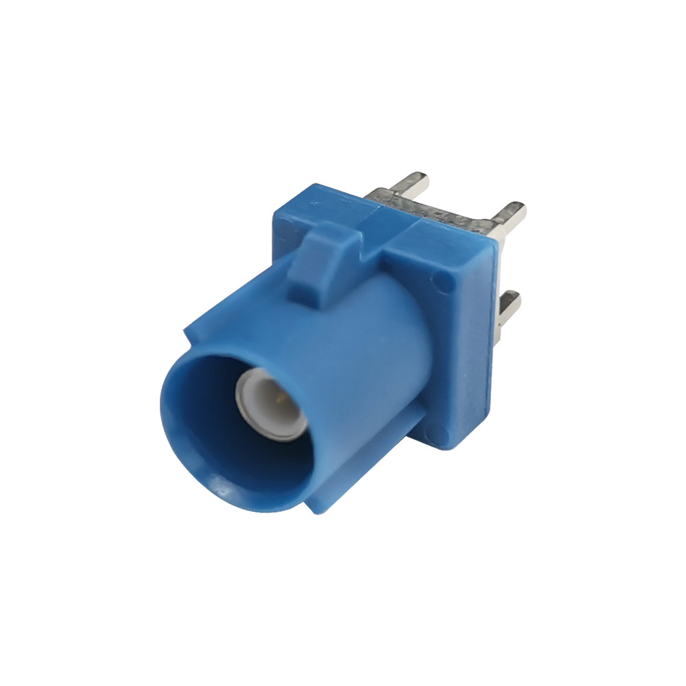
FAKRA and HSD address different electrical requirements and are not interchangeable.
Selection factor | FAKRA | HSD |
|---|---|---|
Primary signal type | RF or compatible coaxial data link | High-speed differential data |
Nominal impedance | 50 ohms | 100 ohms differential |
Basic construction | Coaxial interface | Four shielded signal contacts |
Typical uses | GNSS, radio, cellular, antennas, selected SerDes camera links | Compatible cameras, displays, LVDS, USB and data links |
Cable type | Automotive coaxial cable | Shielded differential cable |
Coding | Mechanical and color coding | Mechanical and color coding |
Directly interchangeable | No | No |
Practical Selection Process
Start with the signal rather than the connector appearance:
Is the connection carrying an RF antenna signal?
Is it a coaxial serialized-data link?
Is it carrying high-speed differential data?
What impedance does the module require?
Which protocol and data rate are specified?
What is the channel-loss budget?
Does the installation require a sealed connector?
Which mechanical code prevents mismating?
Is the requirement for a connector or a tested cable assembly?
GNSS, cellular, and antenna links generally lead to a FAKRA evaluation. Compatible LVDS, USB, camera, and display interfaces may lead to HSD. The module specification and vehicle-level validation plan should determine the final choice.
When Both Connector Systems Are Required
A vehicle can use multiple FAKRA and HSD connections. For example, a telematics unit may use FAKRA for GNSS and cellular antennas, while an infotainment or camera system uses HSD for high-speed differential data.
Working with one manufacturer for connectors, adapters, and cable assemblies can simplify mating-interface confirmation, drawing control, prototype builds, validation, and production traceability.
How to Specify a Reliable Cable Assembly
Define the Electrical Requirements
For a FAKRA assembly, provide:
Nominal impedance
Operating-frequency range
Insertion-loss requirement
Return-loss or VSWR requirement
Coaxial cable type
Shielding and grounding requirements
For an HSD assembly, provide:
Differential impedance
Protocol and data rate
Frequency-dependent channel requirements
Cable type and maximum length
Pinout
Shielding requirements
Whenever possible, include the mating connector part number, module drawing, or controlled interface specification. A photograph alone rarely provides enough information for reliable selection.
Define Mechanical and Environmental Conditions
A complete RFQ should also state:
Connector code, color, and configuration
Cable length and tolerance
Cable exit direction
Minimum bend radius
Operating-temperature range
Vibration and mechanical-load requirements
Sealing or ingress-protection level
Clips, labels, sleeves, and strain relief
Packaging and traceability requirements
Prototype and annual production quantities
Define Validation and Documentation
Required testing should be established before samples are manufactured. Depending on the project, the validation plan may include:
Continuity and short-circuit testing
Insulation and contact resistance
Dimensional and visual inspection
Terminal-retention or pull-force testing
FAKRA insertion-loss and VSWR measurements
HSD differential-impedance and channel testing
Vibration and environmental testing
Ingress-protection testing for sealed assemblies
First article inspection or PPAP documentation
Material and RoHS declarations
North American automotive projects may also reference SAE/USCAR requirements. The official USCAR EWCAP specification resources include documents covering connector testing, connector design, coaxial connectors, and wire crimping. The customer should identify the applicable specification and revision; suppliers should not assume that every program uses the same acceptance criteria.
Why Work with a Specialized FAKRA and HSD Manufacturer?
A specialized manufacturer should provide more than a catalogue part number. Engineering support is valuable when a project includes unusual cable lengths, limited installation space, multiple coding requirements, alternative-source qualification, or customer-specific validation.
Relevant capabilities may include:
FAKRA and HSD connectors, adapters, and cable assemblies
Cable-end and PCB-end configurations
Custom cable length, pinout, coding, and exit direction
Drawing and mating-interface review
Prototype, sample, small-batch, and volume-production support
Controlled crimping and termination processes
Electrical and dimensional inspection
Lot identification and production traceability
Project-specific quality documentation
Quality claims should be supported by measurable evidence. Ask prospective suppliers about inspection equipment, test methods, process controls, calibration, traceability, sample reports, and documentation capability—not simply whether they offer “high quality” or a “competitive price.”
Frequently Asked Questions
Are FAKRA and HSD connectors interchangeable?
No. FAKRA is primarily a 50-ohm coaxial interface, while HSD is a nominal 100-ohm differential interface. They have different electrical structures and cannot replace each other directly.
Which connector is suitable for an automotive camera?
It depends on the camera architecture. A compatible serialized coaxial link may use FAKRA. A compatible LVDS or differential data link may use HSD. Check the camera, ECU, SerDes, impedance, and complete channel specifications before selecting the connector.
Can every HSD cable support automotive Ethernet?
No. Ethernet compatibility depends on the physical layer, pinout, connector variant, cable construction, channel length, and validation requirements. Mechanical compatibility alone is insufficient.
Are all FAKRA and HSD connectors waterproof?
No. Sealed versions must be selected for exposed environments. The complete mated assembly—including the seals, cable, termination, and enclosure—must be tested under the specified conditions.
What information is required for a custom quotation?
Provide both mating interfaces, connector codes, pinout, cable type, length, frequency or protocol, data rate, environmental requirements, validation requirements, sample quantity, annual volume, and available drawings.
Conclusion: Select the Complete Connection System
FAKRA and HSD perform distinct but complementary roles in ADAS and autonomous-driving architectures. FAKRA is generally selected for RF antenna connections and compatible coaxial data links. HSD is used for compatible high-speed differential connections involving cameras, displays, infotainment units, and other data modules.
Reliable selection requires the connector, cable, termination, PCB transition, mating interface, and operating environment to be evaluated as a complete system.
Developing an ADAS, camera, antenna, or vehicle data project?
Send our engineering team your application details, mating-interface part numbers, connector codes, pinout, cable length, frequency or data protocol, environmental requirements, drawing, sample quantity, and estimated annual volume.