What Is an HSD Connector for Automotive Ethernet and Infotainment Systems

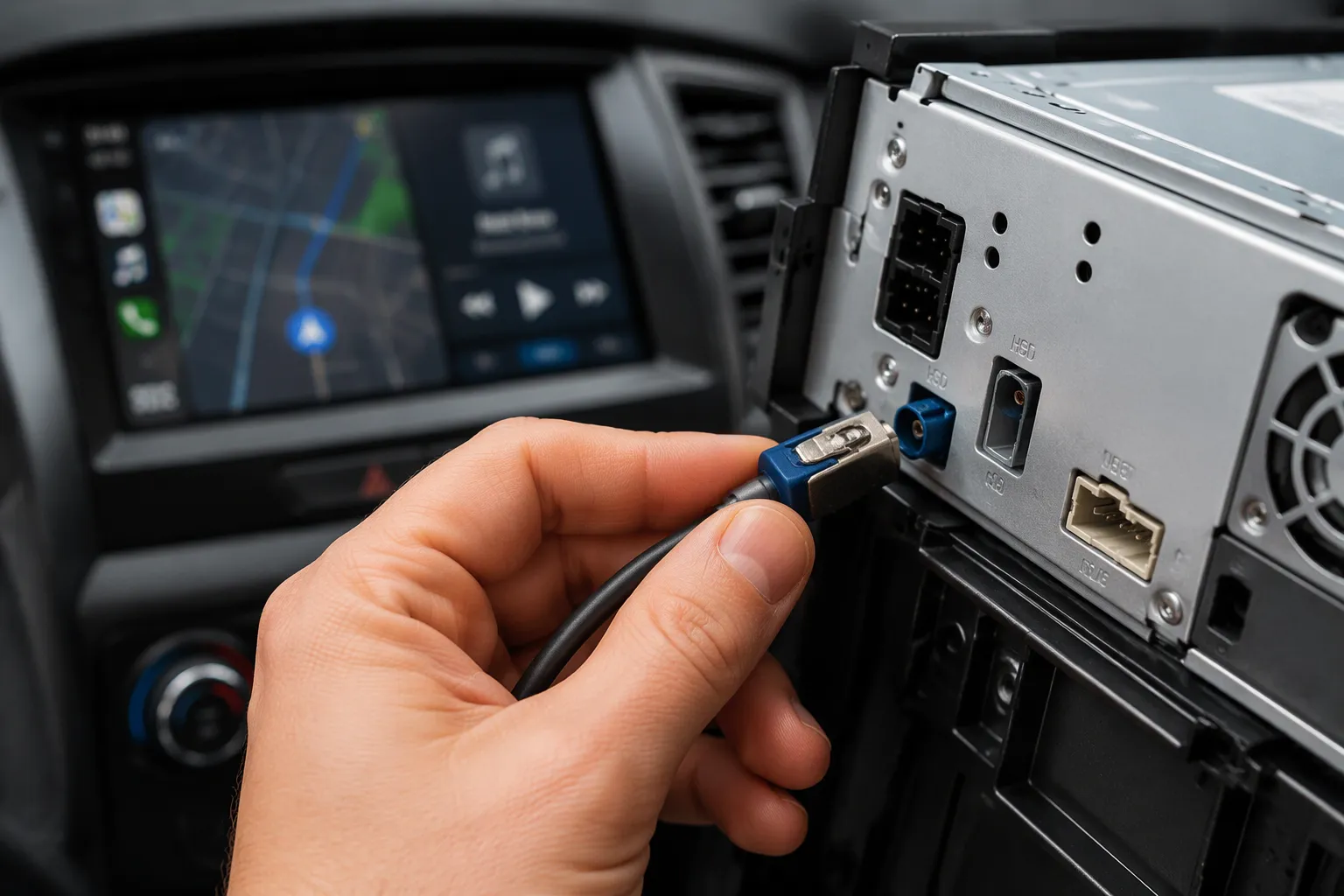
A buyer checks a replacement cable for a vehicle display module. The part must fit the existing housing, pinout, and routing path before the order ships. A high speed data (HSD) connector is a shielded, differential interconnect for automotive data transmission. It carries high-speed signals in infotainment systems and hsd connector automotive ethernet links. These links support cameras, displays, and control modules in modern automobiles. A wrong pin assignment, weak shielding, or incorrect cable length can degrade signal integrity, cause connector mismatch, or make installation difficult.
In Short: An HSD link is shielded and differential. Confirm pinout, impedance, shielding, coding, and cable length before ordering.
Key Takeaways
Confirm pinout, impedance, shielding, coding, and cable length before you order an HSD connector.
The HSD connector family name does not guarantee protocol compatibility; validate a sample in your actual system.
Measure cable length along the real routing path, including brackets and slack, not in a straight line.
Choose a right-angle HSD connector for tight spaces; choose a straight connector for open axial clearance.
Use a written checklist to confirm application, protocol, gender, coding, pinout, cable type, and length before release.
What Is a High Speed Data (HSD) Connector?
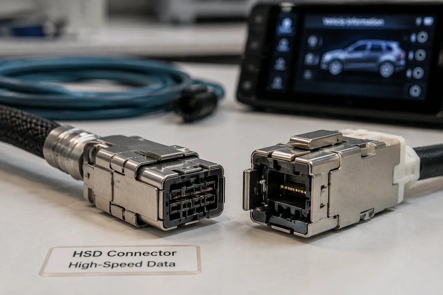
HSD stands for High-Speed Data. A high speed data (HSD) connector is a shielded, multi-contact interface. It carries differential digital data transmission inside vehicles. Engineers use high speed data connectors to move video, camera, and sensor data between modules. The hsd connector automotive ethernet link is one common use case. Another use case is infotainment video. A third use case is USB data.
Structure of an Automotive HSD Connector
An automotive high-speed connector contains five main parts. The housing holds the contacts and provides the mechanical body. Terminals carry the electrical signal. A metal shield surrounds the contact area and blocks outside noise. The cable attaches to the rear of the housing through a crimp joint. Locking features keep the mated pair secure under vibration.
Each part affects performance. The housing material controls dimensional stability. Terminal plating affects contact resistance. Shield coverage and cable construction set the noise rejection level. The exact electrical performance depends on the specific connector and cable assembly. Buyers cannot judge a part by its family name alone. They should compare datasheet values against the system requirement.
High-speed connectors also include coding features. Different codings on the plastic housing prevent wrong mating. Primary and secondary locks add retention force. These features matter in production assembly and service work. A secure lock also protects the signal path from intermittent contact. Buyers should compare high-speed connectors by coding, lock type, and shield design.
HSD Connector Automotive Ethernet Role
Automotive Ethernet uses differential signaling. Two wires carry equal and opposite signals. The receiver reads the voltage difference between them. This method rejects common-mode noise from the vehicle electrical system.
The hsd connector automotive ethernet relationship depends on several factors. Pair balance keeps the two signal lines symmetrical. Good balance lowers crosstalk and preserves signal integrity. Shielding blocks electromagnetic interference from nearby power cables. Cable termination controls reflections at the mating interface. Connector and cable compatibility ensures the impedance stays consistent along the path. Each factor shapes the eye pattern at the receiver.
The connector name alone does not determine protocol compatibility. A part in this family may suit one protocol and fail another. Buyers must confirm the electrical design and test requirements. Protocol-specific validation is the only reliable proof. A sample test in the target system settles the question.
Automotive ethernet connectors must also match the cable. A high-speed plug paired with the wrong cable loses performance. The same rule applies to in-vehicle ethernet links. The assembly, not the part alone, defines the channel.
High-speed data transmission also depends on pair geometry. Twisted pairs hold impedance stable along the cable. Poor geometry raises insertion loss and return loss. These losses shrink the link margin. A short cable with clean termination often beats a long cable with poor shielding.
High-speed routing demands care. Keep cables away from motors and power feeds. Confirm the bend radius before installation. A crushed cable changes impedance and ruins the network. Route cables along the harness path the vehicle team approved.
Not every high-speed data assembly supports every protocol. USB, LVDS, and Ethernet each set different requirements. Buyers of automotive connectors should request drawings and test data for the exact application. They should also validate a sample in the real system.
High-Speed Performance: Impedance and Signal Integrity
Impedance matching keeps an automotive high-speed connector working across the link. Differential impedance describes the opposition a signal pair presents to the traveling wave. Return loss measures signal reflection at an interface. Insertion loss measures signal lost along the channel. Crosstalk measures coupling between adjacent pairs. Pair geometry, cable length, connector termination, and pin assignment all shift these values.
The required impedance depends on the application and system design. Certain automotive applications use 100-ohm differential systems. Buyers must confirm that value for the actual product. A mismatch at the connector termination creates reflections. Those reflections erode the eye pattern. High-speed and stable data transmission in an hsd assembly starts with a matched channel.
Impedance Matching for High-Speed Data
High-speed data exchange depends on a consistent channel. The cable and termination must share the same target impedance. A change at any point causes a reflection. Pin assignment also matters. A swapped pair breaks differential balance. The receiver then sees noise instead of a clean difference signal. High-speed transmission suffers most at the interfaces. Engineers should review the drawing and confirm the pinout before release.
Data transmission rates rise with each vehicle generation. Higher rates punish small errors. A short cable with clean termination often outperforms a long cable with poor geometry. Buyers should request test data for the exact assembly.
Shielding and Interference Resistance
Shielding blocks electromagnetic interference from motors, power feeds, and nearby wiring. Vehicle electrical noise is constant. A special shielding design keeps that noise away from the signal pair. Cable construction sets the baseline. Connector shielding extends protection through the mating interface. Grounding and termination complete the path. A shield without a good ground connection offers little value.
Routing near power cables raises crosstalk. High-speed connectors with full shield coverage resist this coupling better. High speed data links in tight harness paths need extra care. Installers should keep cables away from strong interference sources. They should also confirm the bend radius. A crushed shield loses effectiveness. No supplier should claim specific shielding performance without test data for the exact cable assembly.
Connector Coding, Keying, and Cable Routing
Coding and Keying to Prevent Mismating
Coding and keying stop a plug from entering the wrong receptacle. Each code uses a distinct housing pattern. A coded pair mates only with its matching counterpart. This design prevents mismating between the vehicle-side harness and the module-side interface. It also blocks incorrect installation during production assembly. A technician who reaches for the wrong cable finds that it will not seat.
Keying supports serviceability as well. A service technician can identify the correct branch by its code. Wiring errors drop, and diagnostic time falls. Buyers should confirm the coding, housing configuration, mating interface, pin assignment, and connector gender before ordering. A gender mix-up or a wrong code turns a simple order into a return.
Cable Length, Routing, and Connector Orientation
Cable length starts with the real routing path. The buyer measures along the harness route, not in a straight line. The measurement must include the distance around brackets and panels. It should also allow slack for installation and service movement. Excess unused cable adds weight and invites coil damage. Sharp bends, crushing, and tension at the connector all harm the link. The buyer confirms the required bend radius with the supplier and checks the location of both modules.
Orientation shapes the routing plan. A straight plug sends the cable out along the mating axis. A right-angle plug turns the cable exit ninety degrees. The table below compares the two styles.
Factor | Straight Connector | Right-Angle Connector |
|---|---|---|
Installation space | Needs axial clearance behind the port | Saves depth behind the port |
Cable exit direction | Straight back from the mating face | Turns along the housing side |
Routing flexibility | Limited near a wall or panel | Follows tight paths near panels |
Connector access | Easy to grip and pull | Harder to reach in tight spots |
Clearance near panels and brackets | Can conflict with a rear panel | Fits close to a bracket |
Mechanical strain | Bending load falls on the cable | Housing absorbs the bend |
Compact vehicle packaging | Less suited to shallow cavities | Well suited to shallow cavities |
High-speed connectors with the wrong exit direction force a bend right at the plug. That bend strains the termination. High-speed links suffer most at this point. A right-angle hsd plug often solves a packaging conflict. The buyer should match the style to the cavity, then confirm the drawing.
HSD Applications and LEADSIGN Cable Assemblies
Infotainment, Displays, Cameras, and Control Modules
Automotive high-speed connector assemblies serve many cabin systems. Head units, center displays, digital instrument clusters, and rear-seat entertainment screens all move video and control data. Camera and video links feed driver-assistance views. USB ports connect phones and media devices. LVDS display connections carry pixel data. An hsd connector automotive ethernet link joins control modules when the configuration is validated for that protocol. The ivi infotainment domain relies on these links to keep advanced information and entertainment systems responsive.
One standard assembly does not automatically support USB, LVDS, Ethernet, or video. Pinout, impedance, shielding, cable construction, and protocol requirements must be confirmed for each interface. The assembly must match the actual system interface and pinout. A head unit port and a display port may look alike yet carry different signals. Buyers should verify the drawing before release.
LEADSIGN supplies automotive connectors and cable assemblies for these roles. The range includes HSD connectors, HSD cable assemblies, HSD LVDS cables, and HSD USB cable assemblies. Related options include automotive high-speed data cables, FAKRA connectors, and custom automotive cable assemblies. Each product supports high speed data transmission when the design matches the application.
Standard vs. Custom HSD Cable Assemblies
A standard assembly fits a known connector combination, a known length, and standard routing. It suits repeated purchasing and a stable production design. The buyer orders the same part number and receives the same build.
A custom assembly is preferable in several cases:
Special cable length or different connector configurations
Straight-to-right-angle design for limited installation space
Special coding or a specific pin assignment
Multi-branch design for several modules
Prototype development, low-volume projects, or OEM integration
Aftermarket infotainment installation
Custom work also helps when an installer needs a specific length for a tight cavity. The hsd assembly then follows the real routing path. High-speed connectors and cable must stay matched through the build. Buyers should send the application, protocol, pinout, length, and routing details with each request. LEADSIGN reviews those details and proposes a configuration for approval.
HSD vs. FAKRA and the LEADSIGN Procurement Checklist
Performance, Application Fit, and Cost Compared
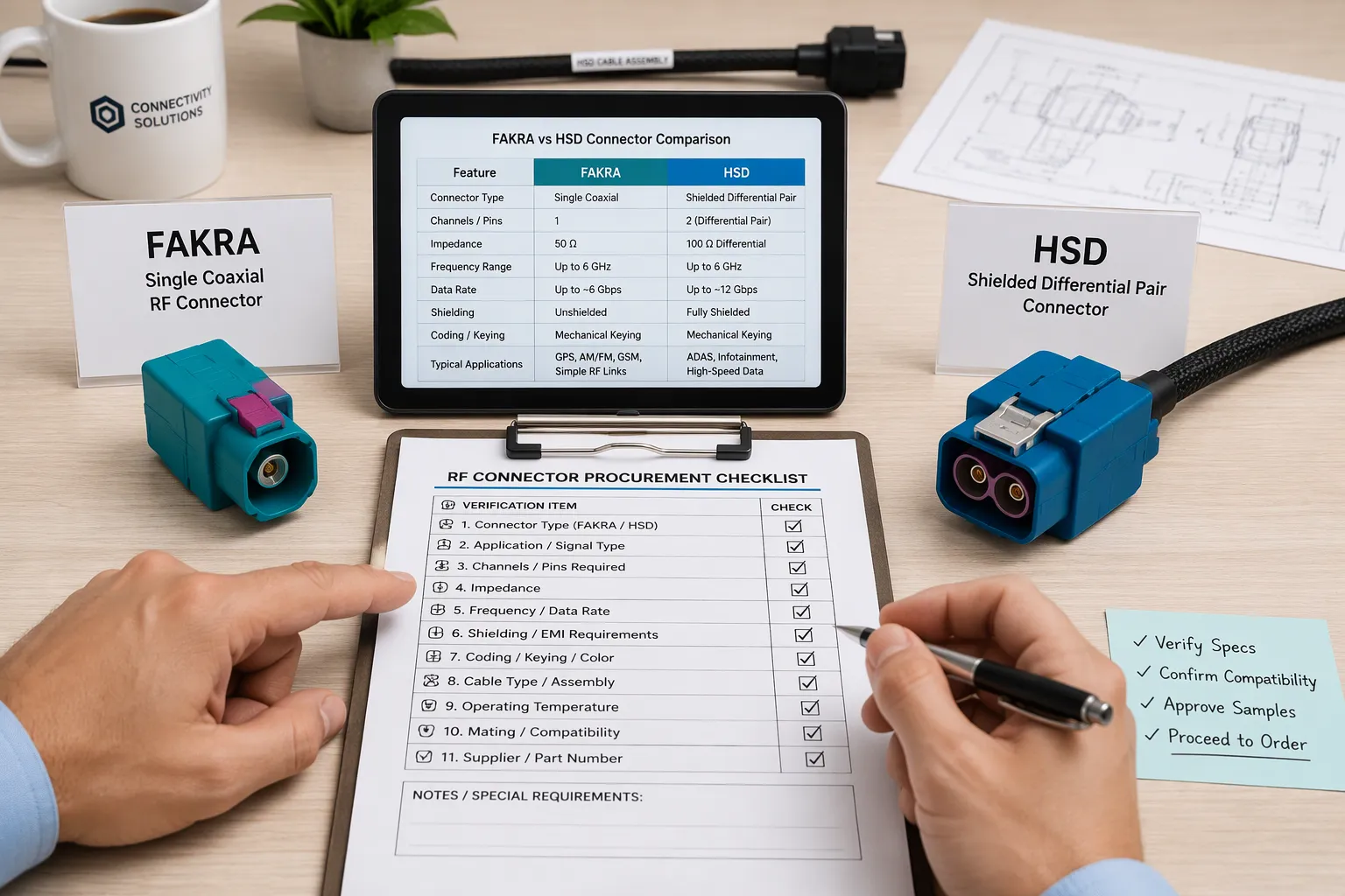
HSD and FAKRA connectors serve different jobs in a vehicle. FAKRA connectors carry radio frequency signals. They suit antennas, GPS, and broadcast receivers. HSD connectors carry differential digital data. They suit infotainment video, camera links, and the hsd connector automotive ethernet path when the design is validated for it. Each family fits its own application best.
Performance differs by design intent. FAKRA focuses on controlled impedance for RF bands. HSD focuses on pair balance and shielding for high-speed digital streams. A buyer who needs high-speed data transmission should start with the digital family. A buyer who needs an antenna feed should start with the RF family.
Cost tracks volume and complexity. Both families use similar housing and terminal processes. The assembly cost depends more on cable type, length, and connector count than on the family name. Neither option is inherently cheaper for every project. The application decides.
What to Confirm Before Ordering
A written checklist prevents most order errors. The table below lists the points a buyer should settle before release.
Specification | Why It Matters | What the Buyer Should Confirm |
|---|---|---|
Vehicle application | Sets the system context | Module name and location |
Data protocol | Defines electrical needs | Protocol and validation plan |
HSD connector family | Sets the mating interface | Family and series |
Connector gender | Prevents a non-mating pair | Plug or receptacle |
Connector coding | Blocks wrong mating | Code letter or pattern |
Pin assignment | Protects signal balance | Pinout against the drawing |
Cable type | Sets impedance and loss | Cable construction and jacket |
Cable length | Affects loss and fit | Measured routing path |
Cable exit direction | Shapes the route | Exit angle and clearance |
Straight or right-angle design | Fits the cavity | Style per port location |
Shielding structure | Resists interference | Shield type and coverage |
Impedance requirement | Preserves signal integrity | Target value for the system |
Number of connectors | Sets branch count | Count per harness |
Branch configuration | Matches module layout | Branch points and lengths |
Environmental conditions | Tests durability | Temperature, vibration, moisture |
Required samples | Proves fit | Sample quantity and build |
Drawings | Documents the build | Approved drawing revision |
Validation requirements | Confirms performance | Test plan and acceptance |
Quantity | Sets pricing tier | Annual and release volume |
Packaging and delivery | Protects parts in transit | Label, pack, and schedule |
Common mistakes repeat across projects. Some buyers choose by appearance only. Others assume all high-speed connectors support the same protocol. A missed pin assignment or a confused gender stops assembly. A wrong coding or an incorrect cable length forces a reorder. Weak shielding, a tight bend radius, or routing near strong interference sources degrades the link. Skipping the drawing review or the sample test hides these faults until production. Assuming one application's cable suits another adds risk.
LEADSIGN supports connector selection, cable length planning, interface matching, cable routing review, connector configuration, and custom assembly work. The team also supplies automotive connectors and high speed data assemblies for infotainment and the ivi domain. Buyers can contact LEADSIGN for HSD connector information, assembly selection, custom configuration, technical drawings, samples, and automotive connector quotations.
The HSD connector serves as a foundational building block for vehicle intelligence. Its shielding, high-speed data capability, and compact design meet the demands of Ethernet links and infotainment systems. These traits map directly to cockpit displays, camera links, and connected vehicle modules. The same high-speed data path supports the ivi domain in production vehicles. Final compatibility still depends on the actual vehicle system, pinout, drawing, and validation requirements. Automotive buyers should confirm each detail before release.
HSD and FAKRA each fit different design priorities. Selection should follow application requirements. Readers can contact LEADSIGN for technical consultation, samples, customization, or a quotation.
FAQ
Does an HSD connector always support automotive Ethernet?
No. The connector family name does not guarantee protocol compatibility. Ethernet support depends on the electrical design, pin assignment, shielding, termination, and validation for that specific link. A buyer should request test data and confirm the requirements against the actual system before release.
How does a buyer confirm the correct coding and gender?
The buyer compares the module port and the harness drawing. The drawing lists the code pattern, housing configuration, and plug or receptacle side. A sample fit check settles any doubt. A coded pair mates only with its matching counterpart, so a wrong code fails at installation.
What is the best way to measure HSD cable length?
The buyer measures along the real harness route, not in a straight line. The path must include brackets, panels, and slack for service movement. The buyer then confirms the bend radius with the supplier. Excess cable adds weight, and a tight bend strains the termination.
When should an installer choose a right-angle HSD connector?
A right-angle plug suits shallow cavities and tight panel clearance. It turns the cable exit along the housing side and absorbs the bend. A straight plug fits open axial space. The cavity shape and port location decide the choice, and the drawing confirms it.
What should a buyer send with an HSD quotation request?
The request should include the application, protocol, connector family, gender, coding, pinout, cable type, length, exit direction, shielding needs, and environmental conditions. Drawings and sample quantities help. LEADSIGN reviews these details and proposes a configuration for approval before production.
See Also
Key Benefits of HSD Connectors for Automotive Infotainment Systems
Why HSD Connectors Offer Major Benefits in Automotive Systems
Why HSD Connectors Play a Critical Role in Automotive Industry
Understanding the Fundamentals of HSD Connectors in Automotive Industry