Common Causes of Signal Loss in HSD LVDS Cables

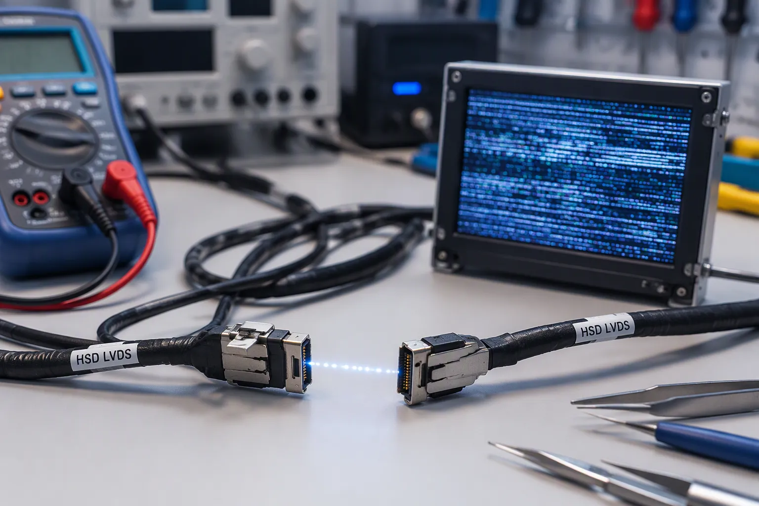
Signal loss in HSD LVDS cables stems from several sources: impedance mismatch, attenuation, electromagnetic interference, poor termination, cable quality, length, physical damage, and environmental factors. This article examines LEADSIGN HSD LVDS cable assemblies and HSD Z Code applications in automotive LVDS displays, rear-view cameras, infotainment, and ADAS video links. Engineers must distinguish HSD from FAKRA. HSD carries shielded high-speed differential data; FAKRA handles 50-ohm coaxial RF. They are not interchangeable. Continuity tests alone cannot prove high-speed LVDS performance. Technicians need deeper troubleshooting methods to diagnose signal loss in bus cables effectively.
Key Takeaways
Continuity tests only check if copper paths connect. They cannot prove a cable will work at high speeds.
Impedance mismatch causes reflections that weaken the signal. Keep impedance consistent from cable to connector to PCB.
Longer cables lose more signal strength. Choose the right cable length and type for your application.
Electromagnetic interference from other electronics can disrupt the signal. Proper shielding and grounding block this interference.
Loose connectors, physical damage, and wrong replacements cause signal loss. Always use the correct HSD cable and follow proper routing.
What Signal Loss Means in HSD LVDS Cables
Signal loss in HSD LVDS cables describes any reduction in the strength or clarity of a high-speed data signal as it travels from transmitter to receiver. In low-voltage differential signaling, the driver sends two complementary voltages down a twisted pair. The receiver reads only the difference between these two lines. Any degradation of that difference — through attenuation, reflection, or noise — directly threatens the link.
Differential Signaling and Common-Mode Rejection
A differential pair carries two voltage signals equal in magnitude but opposite in polarity. The receiving circuit responds to the difference between the two signals, which produces a signal with twice the magnitude of either single line. This balanced arrangement gives the link its noise immunity.
The two conductors carry voltage signals which are equal in magnitude but of opposite polarity. The receiving circuit responds to the difference between the two signals, which results in a signal with a magnitude twice as large. The symmetrical signals of differential signalling may be referred to as balanced, and balanced lines reject common-mode interference when fed into a differential receiver.
When external interference couples onto both conductors almost equally, it creates common-mode noise. Because the receiver subtracts the two lines, this shared noise cancels out. This mechanism, called common-mode rejection, keeps the intended signal intact even in electrically noisy automotive environments. The effectiveness of this rejection depends on how well the two conductors stay balanced along the entire transmission line.
Why Continuity Tests Are Not Enough
A continuity test confirms only that copper paths connect from one end to the other. It cannot verify differential impedance, insertion loss, return loss, shield termination quality, or pair skew. A cable can pass continuity in seconds and still fail at multi-gigabit data rates because the transition geometry is wrong.
What it misses (relevant to LVDS) | |
|---|---|
Open circuits | Improper shielding termination |
Incorrect pin assignments | High-resistance connections |
Basic connectivity | Mechanical strain points affecting impedance |
Damaged insulation or wire strands |
A digital receiver cares about waveform margin, not just copper path continuity. High losses, broken return paths, or length mismatch in differential pairs can close the eye diagram and cause intermittent links. Transition management issues — untwisting pairs, splitting shields, forcing bends — create reflection points and common-mode conversion that continuity testing cannot detect. Technicians must therefore treat continuity as a starting point, not a final verdict on signal integrity.
Top Causes of Signal Loss in HSD LVDS Cables
Impedance Control and Mismatch
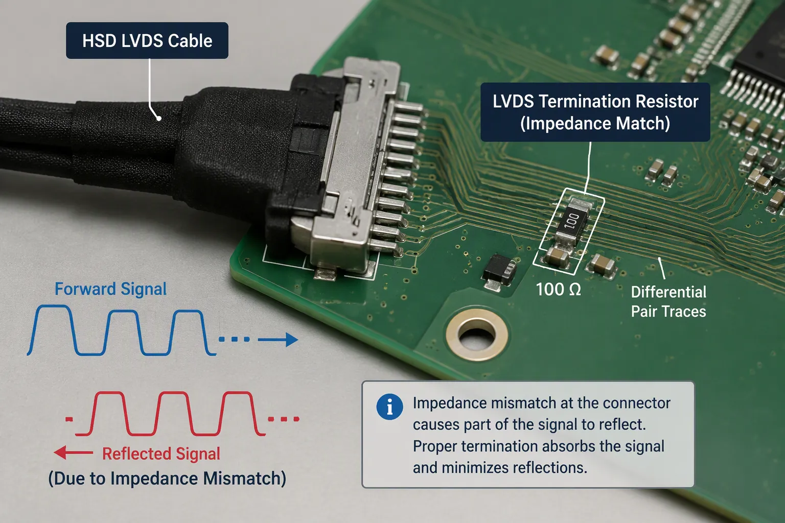
Impedance control stands as the single most critical factor in high-speed data transmission. An LVDS link depends on a consistent characteristic impedance along the entire transmission line. The cable, the HSD connector, the PCB launch, and the termination resistor must all present the same impedance to the traveling signal. When any of these elements deviates from the target value, a portion of the signal reflects back toward the source instead of continuing to the receiver.
These impedance discontinuities create reflections that degrade the waveform. Return loss quantifies the quality of impedance matching at each transition point. A return loss of 17 dB corresponds to a reflected power fraction of about 2 percent, while 20 dB reduces that fraction to 1 percent. Lower return loss values indicate poorer matching and produce more reflections, which increase jitter and close the eye diagram.
Return loss measures impedance matching quality; lower values are better (e.g., <-10 dB). Poor return loss causes reflections, increasing jitter. This principle applies to the PCB launch, HSD connector, and termination points in an LVDS link, where any impedance mismatch will increase return loss and cause reflections that degrade signal integrity.
Engineers must pay close attention to lvds pcb layout when designing the interface between the connector and the driver or receiver. The transition from the cable's controlled impedance to the PCB trace requires careful geometry. Vias, pads, and trace width changes all introduce parasitic capacitance or inductance that shifts the local impedance. A well-designed lvds pcb layout maintains the differential impedance through every transition zone.
The termination resistor also plays a vital role. LVDS receivers typically require a 100-ohm differential termination across the pair at the far end. An incorrect termination value creates an impedance mismatch that reflects energy back down the line. This reflected energy interferes with subsequent data transitions, causing bit errors that appear intermittently.
Attenuation and Excessive Cable Length
Signal attenuation describes the natural reduction in signal amplitude as it travels through a conductor. Every cable exhibits some attenuation per unit length, and this loss increases with frequency. Higher data rates require higher bandwidth, which means the cable must carry higher-frequency components. These components suffer greater attenuation than lower-frequency content.
Insertion loss measures the total signal loss through the cable assembly, including the connectors and any transitions. As cable length increases, insertion loss grows proportionally. The maximum usable length for an HSD LVDS link depends on the selected product and the specific part number. Different cable constructions, conductor gauges, and dielectric materials produce different loss characteristics. Engineers must verify the exact product specification before assuming a particular length will work.
Cable attenuation becomes especially problematic in automotive applications where cameras and displays sit far apart. A rear-view camera mounted at the back of a vehicle may need to send video data to a display in the dashboard. The distance between these points can exceed several meters. At that length, the accumulated losses may push the signal below the receiver's threshold.
Channel losses include not only the cable itself but also the connectors, PCB traces, and any splices or adapters in the path. Each connection point adds a small amount of loss. When engineers sum all these contributions, they can estimate whether the total insertion loss remains within the link budget. If the budget exceeds the receiver's sensitivity, the link fails.
Engineers can mitigate attenuation by selecting a cable with lower loss per meter, reducing the overall length, or adding a repeater or equalizer at an intermediate point. Some systems use cable equalization to boost high-frequency components that suffer the most attenuation. These techniques help maintain signal integrity across longer distances.
The key takeaway remains that signal loss in bus cables accumulates with distance and frequency. A short cable may perform flawlessly, while a longer version of the same construction fails. Designers must calculate the expected losses for their specific configuration and verify that the chosen components meet the required performance. Testing the actual assembly under real operating conditions provides the final confirmation that the link will work reliably.
Physical, Shielding, and EMI Causes
Bends, Crushing, and Routing Damage
Sharp bends and crushing damage alter the geometry of a cable's internal conductors. When a cable bends too tightly, the distance between the two conductors in a differential pair changes. This shift changes the local impedance and creates impedance discontinuities along the line. Pulling or stretching the cable can also deform the dielectric material and permanently change its electrical properties.
Incorrect lvds routing introduces similar problems. A cable routed against a sharp metal edge may develop crushed insulation over time. Vibration accelerates this wear. Technicians should respect the minimum bend radius for the specific cable assembly and provide proper strain relief at both ends. Good lvds routing keeps cables away from heat sources and moving parts.
Electromagnetic Interference and Shield Grounding
Electromagnetic interference from motors, inverters, ignition systems, relays, and switching power supplies can couple onto the signal pair. The shield around an HSD cable blocks much of this energy. However, the shield only works when it connects properly to ground at the connector interface. An incomplete shield termination lets electromagnetic interference reach the conductors and degrade the signal.
Poor shield grounding also converts external noise into common-mode noise on the pair. This noise reduces the receiver's ability to detect the intended difference signal. In severe cases, electromagnetic interference causes bit errors and intermittent video dropouts. Proper shield grounding at both ends of the link is essential for maintaining signal integrity.
Pair Skew and Imbalance
Pair skew occurs when the two conductors in a differential pair have different electrical lengths. This mismatch means the two signals arrive at the receiver at slightly different times. The receiver then cannot perfectly cancel common-mode noise, and the eye diagram closes. Skew also increases crosstalk in lvds designs because the imbalance allows energy to couple between adjacent pairs.
Physical damage, poor manufacturing, or incorrect termination can all introduce skew. Even small differences in conductor length or dielectric properties matter at high data rates. Engineers must verify that the cable assembly maintains tight pair matching. Any imbalance directly increases signal loss and reduces the link margin.
Connector, Termination, and Environmental Causes
Loose HSD Connectors and Incorrect LVDS Termination
A loose HSD connector breaks the signal path in ways that a visual inspection may miss. Incomplete locking allows the connector to back out under vibration. This movement changes the contact resistance and creates intermittent opens. Damaged contacts or incorrect keying force the mating parts together in the wrong orientation. The result is a poor connection that passes low-speed tests but fails at high data rates.
An unsuitable lvds pcb layout compounds these problems. The transition from the connector to the board must maintain controlled impedance. A poor lvds pcb layout introduces stubs, excess capacitance, or long unshielded traces. These defects cause reflections and increase signal loss. Engineers should follow lvds pcb layout guidelines that keep differential traces short and matched. The same guidelines apply to the termination resistor placement. An incorrect termination value or a missing termination resistor reflects energy back toward the source. This poor termination raises return loss and closes the eye diagram. Proper lvds termination requires a matched resistor close to the receiver inputs.
Temperature, Vibration, Moisture, and Poor Repairs
Temperature changes cause materials to expand and contract. This movement stresses solder joints and crimp connections over time. Vibration accelerates wear on connector latches and contact surfaces. Moisture and contamination enter through damaged seals or incomplete locking. Corrosion then attacks the contact plating and raises resistance. These environmental factors slowly degrade the lvds link until it fails.
Poor field repairs introduce additional risks. Incorrect crimping leaves air gaps or loose strands inside the contact. Unsuitable replacement cables may have the wrong impedance or shield construction. Technicians should never substitute a FAKRA coaxial cable for an HSD cable. HSD carries shielded high-speed differential data for selected lvds, USB, Ethernet, and automotive camera applications. FAKRA handles 50-ohm coaxial RF. The two are not interchangeable. A wrong replacement cable creates incorrect termination and guarantees signal loss. Always verify the exact product specification before ordering a replacement.
How Signal Loss in Bus Cables Manifests
Symptoms in Automotive Video and Display Systems
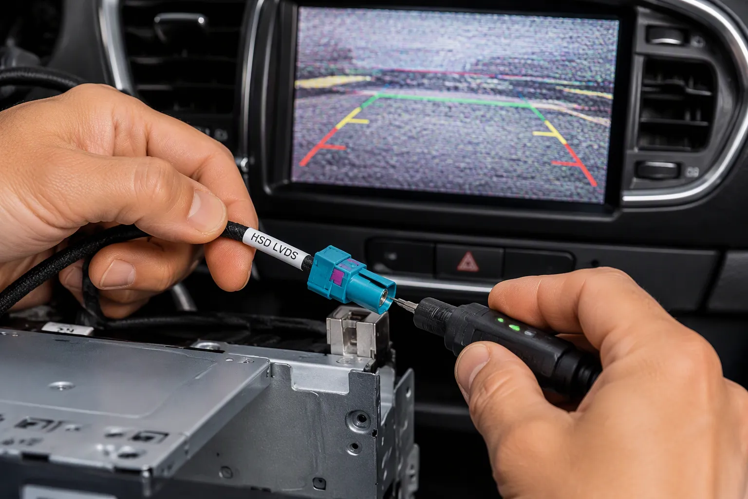
Signal loss rarely appears as a clean, total failure. It usually shows up as ghosting, shadows, image lag, or intermittent video that comes and goes with vibration or temperature. A rear-view camera may display a blank screen one moment and a clear image the next. An LVDS display may show pixel noise, color shifts, or brief black frames. ADAS video links may log data errors without any visible symptom at all.
A 2018 Q5 owner reported a blank rear-view camera after replacing the MMI unit. A scan showed an "LVDS Line No Signal" fault. The issue persisted even after replacing the camera, which proved that component swapping alone cannot isolate the fault. Technicians must test the full signal path instead.
Observed issue | Likely HSD Cable cause | Recommended fix |
|---|---|---|
Intermittent image loss | Loose connector or bend stress | Reseat, inspect routing, replace damaged section |
Signal fails near power load change | Shield damage or EMI exposure | Separate routing and replace shield-compromised cable |
Module recognized only sometimes | Oxidation or terminal contamination | Inspect contacts and replace affected connector assembly |
Fault appears after previous repair | Mismatched HSD Cable replacement | Install specification-matched replacement part |
Practical Troubleshooting Sequence
A systematic approach isolates the fault faster than guesswork. Technicians should follow this sequence:
Confirm the symptom under the same load, temperature, and operating mode.
Inspect each HSD Cable connector for latch wear, pin damage, and shell deformation.
Check routing points for tight bends, pinch marks, abrasion, or contact with sharp edges.
Review nearby electromagnetic interference sources, especially added electronics or modified power wiring.
Use a known-good HSD Cable when possible for controlled substitution.
Recheck after reassembly, because stress can return during panel installation.
This sequence addresses the most common causes of signal loss in bus cables. Technicians should also test conductor and shield continuity, check pair polarity and shorts, and verify differential impedance and termination. When the link still fails, they must measure insertion loss, return loss, crosstalk in lvds designs, and eye margin. These measurements reveal problems that continuity tests cannot detect. A damaged or electrically unsuitable cable assembly must be replaced with a specification-matched part.
Proper lvds routing protects differential pairs from physical stress. Careful lvds routing also keeps cables away from noise sources. Poor shielding or incomplete shield grounding lets electromagnetic interference couple onto the pair. This interference raises signal attenuation and closes the eye diagram. Excessive insertion loss from long cables or poor connections produces the same result. Each of these factors reduces signal integrity and shortens the usable link margin.
LEADSIGN supplies HSD LVDS cable assemblies and customized automotive cable assemblies for these applications. The company offers OEM and ODM support. Engineers and purchasing teams can consult LEADSIGN to match a cable assembly to their specific part number and verify the exact product specification. This support helps teams avoid the mismatched replacements that cause repeat failures.
Signal loss in bus cables stems from impedance mismatch, attenuation, EMI, physical damage, and poor connections. Most issues remain preventable through proper impedance control, correct lvds termination, adequate shielding, careful routing, and thorough testing. Engineers must verify controlled impedance for each specific part number. Continuity tests alone cannot prove high-speed lvds performance. The automotive data cables market reached USD 9.9 billion in 2024, projected to hit USD 28.14 billion by 2033, with Safety and ADAS growing fastest. This growth demands reliable low-voltage differential signaling links. A proper termination resistor, correct lvds termination, and avoiding incorrect termination preserve signal integrity. Teams should apply the troubleshooting sequence and consult LEADSIGN for customized hsd lvds cables. Reliable high-speed automotive data links will only grow more critical.
FAQ
Can a cable pass a continuity test and still lose signal?
Yes. A continuity test only confirms that copper paths connect. It cannot measure differential impedance, insertion loss, return loss, or pair skew. A cable may pass continuity and still fail at high data rates because reflections and imbalance close the eye diagram. Technicians need deeper testing to confirm high-speed lvds performance.
What role does lvds pcb layout play in signal loss?
The lvds pcb layout controls the transition from the HSD connector to the driver or receiver. Poor geometry adds stubs, capacitance, or unmatched traces. These defects cause reflections and raise return loss. Engineers should follow lvds pcb layout guidelines that keep differential traces short, matched, and close to the termination resistor.
Why does cable length matter for lvds links?
Insertion loss grows with cable length and frequency. Longer cables attenuate higher-frequency components more than lower ones. The maximum usable length depends on the selected product and the specific part number. Engineers must verify the exact product specification before assuming a length will work in a given lvds link.
How do technicians find the source of signal loss in bus cables?
They reproduce the failure, inspect connectors and routing, check shield grounding, and test pair polarity. They then verify differential impedance and termination. When needed, they measure insertion loss, return loss, crosstalk, and eye margin. This sequence isolates the fault faster than swapping components. Replacing a damaged or unsuitable assembly restores signal integrity.
Can a FAKRA cable replace an HSD cable?
No. HSD carries shielded high-speed differential data for selected lvds, USB, Ethernet, and camera applications. FAKRA handles 50-ohm coaxial RF. The two are not interchangeable. A wrong replacement creates incorrect termination and guarantees signal loss. Technicians must match the replacement to the exact part number.
See Also
Improving Data Connections Using High-Speed Data Low-Voltage Differential Signaling Cables
Benefits of Low-Voltage Differential Signaling Transmission Lines for Automotive Use Cases
Comprehending Low-Voltage Differential Signaling and Gigabit Video Interface for Fast Video Transfer
Why Low-Voltage Differential Signaling and Gigabit Video Interface Cables Matter in Car Info Systems
Explaining Fakra High-Speed Data Low-Voltage Differential Signaling Four-Pin Connector Types