FAKRA GPS and Galileo Antenna Cable Guide for Automotive Navigation

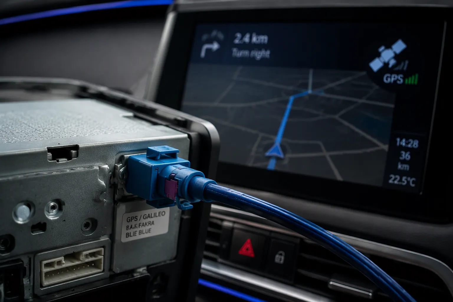
A 50-ohm assembly with correct coding is the usual starting point. FAKRA C (blue) covers 1.2–1.6 GHz, per fakraconnectors.com; it is a connector coding, not a satellite system. Keying, loss, length, and environment decide the final part.
In Short: Begin with a 50-ohm Code C assembly for GPS antenna work, then match connector keying, loss, length, and environment to the receiver interface, harness routing, and vehicle conditions.
The U.S. system, Galileo from the European Union, and GNSS as the general term differ.
Key Takeaways
Use a 50-ohm FAKRA Code C cable for most GPS and Galileo antenna connections in vehicles.
Keep cable length short and use low-loss coax to prevent signal loss and unstable positioning.
Route cables away from power wires and secure them to avoid interference and damage.
Choose FAKRA for factory vehicle harnesses and FAKRA-to-SMA adapters for bench testing or aftermarket devices.
Test the entire antenna path—connector, cable, and receiver—to fix unstable GPS or Galileo fixes.
GPS, Galileo, and GNSS: A Quick GPS & GNSS Antenna Guide
What GPS, Galileo, and GNSS Mean
GPS is the United States satellite navigation system. Galileo is the European Union's system. GNSS is the umbrella term for all satellite constellations that provide positioning, navigation, and timing. Emlid lists the global systems as GPS, GLONASS, Galileo, and BeiDou, plus the regional QZSS and IRNSS services.
System | Operator | Satellites |
|---|---|---|
GPS | United States | 31 |
GLONASS | Russia | 24 |
Galileo | European Union | 23 |
BeiDou | China | 44 |
QZSS | Japan | 4 |
IRNSS | India | 7 |
Emlid reports these satellite counts in its GNSS versus GPS comparison. The chart below, published by Emlid, shows the same comparison visually.
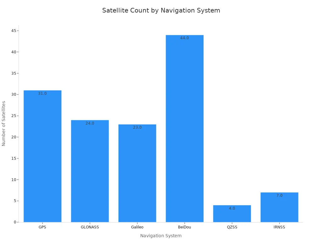
People often say "GPS" when they mean any satellite positioning. Technically, GPS is one part of GNSS. A GPS antenna receives the U.S. signal. A GNSS antenna cable may carry several constellations at once.
How Vehicles Use Multiple Constellations
Most modern GNSS receivers decode signals from more than one constellation at the same time, according to Advanced Navigation. A vehicle therefore may use GPS, GLONASS, BeiDou, and Galileo together through a compatible receiver. Not every vehicle supports every constellation; support depends on the receiver and its software.
Multi-GNSS support does not guarantee better accuracy. Performance depends on the receiver, the antenna, satellite visibility, software, installation environment, and correction services. Galileo does not always outperform GPS. For a closer look at Galileo GPS automotive use cases, see the LEADSIGN article on devices using Galileo GPS precision.
How GPS and Galileo Support Automotive Navigation
A GNSS receiver never reads position from a single signal. It solves a set of equations from many satellites at once, and the answer changes every second.
Role of the GNSS Receiver
The receiver sits at the center of the chain. It supplies position, speed, and time data to the car navigation unit and to telematics modules, Unicore reports. Automotive programs such as infotainment, eCall, and ERA-GLONASS rely on that data stream, Furuno notes.
The receiver also enables functions beyond turn-by-turn routing:
Real-time directions and congestion avoidance, per Caradas.
Vehicle-to-vehicle and vehicle-to-infrastructure hazard warnings.
Lane-level mapping for autonomous and semi-autonomous driving.
A gps antenna alone cannot deliver any of these functions. The receiver must track gps, glonass, beidou, and galileo signals together to hold a stable fix. A second gps antenna on a different module does not fix a weak receiver either.
From Satellite Signal to Vehicle Position
Point One Navigation describes the pipeline in four stages. The antenna captures very weak gps signals from satellites. A low-noise amplifier boosts them above the noise floor. The receiver then correlates each satellite's code to measure pseudorange. Trilateration across four satellites solves position plus clock error. The module finally outputs position, velocity, and time, often in NMEA format, at rates from 1 Hz to 100 Hz.
Standalone code-phase accuracy lands near 1–3 meters, per Point One Navigation. Carrier phase tracking reaches roughly 100 times more measurement precision, using the 19 cm GPS L1 wavelength. Correction services such as RTK push the result toward centimeters. PPP converges in 15–30 minutes, which suits some applications but not all. Galileo contributes extra satellites to the solution, and that geometry helps the receiver reject poor measurements.
Main Components of an Automotive GPS Antenna System
A GNSS antenna system works as one signal path, not as four separate parts. Masterclock notes that the GPS signal arrives very weak, so the antenna usually amplifies it before the signal travels down the cable. Each element in the chain must pass that signal without adding loss or noise.
Antenna, Cable, Connector, and Receiver
The antenna captures satellite signals and, in many automotive designs, amplifies them. The cable carries the signal from the antenna to the receiver. The connector terminates the cable and mates it to the antenna or receiver port. The receiver then computes position, velocity, and time.
These parts differ in function. A gps antenna is an active or passive radiating element. A connector is a mechanical and electrical interface. A complete cable assembly combines the cable, two connectors, and the termination work into one tested part. Buyers who confuse the three often order the wrong interface.
Active vs. passive antennas change the wiring. An active gps antenna holds a low-noise amplifier and draws DC bias voltage from the receiver through the center conductor, per fakraconnectors.com. The shield provides ground. A damaged center contact can cut both the RF signal and the antenna power.
How the FAKRA GPS Cable Connects the Chain
The signal path runs in four stages:
The GNSS antenna receives satellite signals at the roof, dashboard, or glass.
The FAKRA cable assembly carries the signal to the receiver bay.
The GNSS receiver amplifies, correlates, and solves the position fix.
The navigation, telematics, or vehicle control module uses that fix.
Masterclock explains that cable resistance attenuates the signal along this path. Receiver sensitivity is finite, so an excessively long run can push the signal below the detection threshold. Engineers should confirm the antenna-to-receiver distance before specifying the automotive gps antenna cable.
LEADSIGN supplies FAKRA connectors and [FAKRA GPS cables] for this link. An external gps antenna typically mates through a keyed FAKRA plug, commonly Code C. For broader background on constellation support, see our gps & gnss antenna guide.
Why FAKRA Connectors Suit Automotive Antenna Systems
A FAKRA interface carries RF from DC to 6 GHz at 50 Ω impedance, and that range covers GNSS bands with margin. LEADSIGN builds each FAKRA connector to these ratings, plus a temperature window of -40 °C to +105 °C and at least 25 mating cycles. The housing protects the connection from vibration, heat, and moisture. These traits explain why the fakra system became common in vehicle antenna links.
Keying, Color Coding, and Locking
The housing color is a visual aid, not an electrical rating. Bafitop notes that color helps installers identify a signal path during assembly and service. The mechanical key does the real work. It blocks a Code C plug from entering a Code D jack, for example. SigmaRF warns that the reference chart skips the letter J, so nobody should infer a part number from a color photo.
LEADSIGN offers 13 mechanical and colored codings plus one neutral coding. TE describes a comparable family with 14 key codes in sealed and unsealed versions. Two locks secure each connection. The primary latch clicks into place on full mating. A secondary lock, often a connector position assurance clip, stops release under heavy vibration, per Metabee. Metabee also lists a retention force above 110 N for the mated pair.
Feature | LEADSIGN FAKRA rating |
|---|---|
Impedance | 50 Ω |
Frequency range | DC to 6 GHz |
Codings | 13 keyed and colored, plus 1 neutral |
Mating cycles | ≥ 25 |
Temperature range | -40 °C to +105 °C |
Compliance | RoHS, WEEE, ELV |
Sealed versions add O-rings and silicone seals. Metabee reports IP67 or IP69K ratings for these parts, which suits exterior antennas and sensors. Heilind lists USCAR 17 as a related specification for the connector family.
Automotive Standard: FAKRA Code C for GPS
Code C is the usual choice for a gps antenna feed. Taoglas sells a GPS/Galileo magnetic mount antenna with a FAKRA Code C jack. 2J Antennas ships its 2JW1001-FKC with a fakra c blue female connector as standard. That part number shows the common pairing: fakra c blue connectors on one end, a receiver port on the other. Installers often call the mating plug a fakra c blue plug, and the pair forms the industry standard for gps/gnss connectivity in many vehicle programs.
Code D also appears depending on the application. Some receivers and antenna modules use it for a different RF path. Buyers should confirm the receiver port before ordering. A keyed housing will not mate with the wrong code, and that error surfaces at the assembly line rather than in the field.
A FAKRA connector does not improve satellite accuracy by itself. It passes the signal with low reflection and holds the connection tight. The antenna, receiver, and installation still set positioning performance. For the full connector range, see [FAKRA connectors].
Automotive GPS Antenna Cable Selection Factors
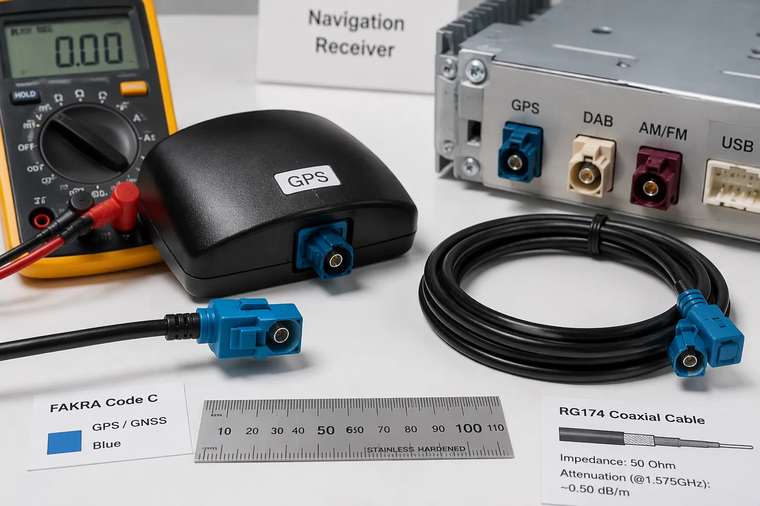
A GNSS receiver cannot recover signal that the cable path destroys. Selection therefore starts at both interfaces and works inward toward the harness.
Interface, Coding, and Connector Type
The antenna port and the receiver port define the assembly. Confirm both before choosing anything else. A roof-mounted gps antenna may end in a FAKRA jack, while the navigation unit may expect a different RF interface. Siretta warns that similar-looking miniature connectors are not interchangeable. The cable connector must match the exact receptacle named on the receiver datasheet.
Coding comes next. A fakra housing carries a mechanical key and a color. The key blocks wrong mating, and the color speeds identification on a crowded harness. Code C, commonly fakra c blue, serves many GPS/Galileo antenna feeds. Code D appears depending on the application. Gender matters too. A jack on the antenna needs a plug on the cable. A right-angle plug may clear a tight cavity where a straight body cannot.
Connector type follows the layout. Siretta compares common embedded options in the table below.
Connector type | Layout suitability |
|---|---|
U.FL/I-PEX | Saves board space; allows antenna placement away from the receiver |
Solder pads | Suits direct soldering of a pre-stripped cable to the PCB |
MMCX | Suits different layouts |
SMA | More robust but usually too large for compact embedded layouts |
Automotive programs usually stay with FAKRA at the vehicle level. Bench fixtures and aftermarket modules often use SMA instead. That split creates demand for [FAKRA to SMA cables].
Length, Shielding, Routing, and Environment
Cable length sets loss. Logistimatics reports that standard RG174 cable loses roughly one decibel of gain per meter. TEJTE publishes a fuller comparison at the GPS L1 band.
Cable | Loss at 1.575 GHz (dB/m) | Typical passive run |
|---|---|---|
RG174 | ~1.2–1.5 | 2–3 m |
RG316 | ~0.9 | 3–4 m |
LMR100 | ~0.82 | 4–5 m |
RF1.13 | ~2.3 | 1 m or less |
RF0.81 | ~3.1 | 0.5 m or less |
A long route may need a lower-loss coax or an active antenna with a compatible bias supply. Logistimatics advises an active gps antenna with a high-gain amplifier once a fleet run exceeds three meters. Siretta adds a caution: more gain is not automatically better, and the antenna must match the receiver's DC bias voltage and current.
Shielding blocks interference. Route the cable away from ignition systems and other antennas, per Logistimatics. Keep bend radius within the coax datasheet limit. Respect the operating temperature window; LEADSIGN rates its FAKRA parts from -40 °C to +105 °C. Plan for vibration with clips and strain relief, and specify sealed housings where moisture is possible. Choose straight or right-angle bodies by the exit direction at each port. For ready-made options, see [FAKRA GPS cables].
How Cable Length and Shielding Affect Signal Quality
Loss, Interference, and Grounding
Every meter of coax removes part of the signal. The center conductor and dielectric absorb RF energy, and that loss grows with frequency and run length. A long path therefore delivers a weaker signal to the receiver. The gps antenna may perform well, yet the link still fails.
Shielding and grounding control noise. A damaged braid lets outside energy reach the center conductor. Poor grounding gives interference a return path into the receiver. A study published in PMC explains that C/N0 detectors cannot separate rising interference from falling signal power. Metal structures attenuate the signal strongly, while window directions pass it better. Engineers should treat a weak fix as either a loss problem or a noise problem until they test both.
Practical Routing Guidance
Route the run with care. Asialeren and LX Antenna give consistent advice:
Keep the path away from high-current power cables, ignition systems, alternators, electric motors, and inverters.
Secure the run against vibration and strain.
Match impedance to the antenna and receiver, typically 50 ohms.
Choose low-loss coax for long runs; Asialeren cites RG-142 for passive runs up to 10 feet and RG-58 up to 6 feet.
Hold the minimum bend radius at 10 times the diameter, per Asialeren.
Seal exterior connectors with self-amalgamating tape, then add UV-resistant tape.
Construction follows the route. A short interior run may accept rg174 cable, while a long roof-to-dash path needs lower-loss coax. The rg174 suits tight cavities where loss matters less. Installers should confirm receiver bias voltage and gps antenna gain before finalizing the assembly.
FAKRA vs. FAKRA-to-SMA for GNSS Systems
A FAKRA port and an SMA port serve different levels of the vehicle architecture. The FAKRA interface belongs to the production harness. The SMA interface belongs to bench equipment, aftermarket modules, and prototype hardware. A FAKRA-to-SMA adapter joins the two worlds without cutting the factory cable.
Where Each Interface Fits Best
Native FAKRA suits any link that stays inside the vehicle. Factory stereos from Ford, BMW, VW, Audi, and Mercedes use FAKRA blue C for GPS, according to fakraconnectors.com. A FAKRA-to-SMA adapter bridges that automotive gps antenna connector to an SMA port on a telematics box, test receiver, or RF module. Common uses include GNSS receiver testing, telematics development, aftermarket installation, and prototype validation.
A vehicle's FAKRA blue C connector links to a spectrum analyzer or GNSS simulator for receiver validation.
An aftermarket GPS tracker with an SMA port connects to a factory gps antenna.
A retrofit navigation box joins an older vehicle's factory antenna feed.
A bench setup swaps between receivers without replacing the factory cable.
Romtronic notes that FAKRA Z to SMA assemblies connect roof-mounted antennas to GNSS modules, where stable impedance and shielding prevent positioning drift. A typical setup uses a short HFC RG-316/U cable with FAKRA on one end and SMA on the other, at 20 cm to minimize loss at the GPS L1 frequency.
Adapter and Extension Considerations
Every adapter adds two extra interfaces, and each one is a potential failure point, per Alibaba's mini FAKRA guide. That guide advises native FAKRA for new hardware and reserves SMA adapters for legacy compatibility. Automotive RF is standardized at 50 Ω, so buyers should confirm impedance on both sides. Active antennas also need DC pass-through through the adapter; passive units do not.
Extension cables solve reach problems in the same way. A short rg174 jumper may cover a tight cavity, while a longer run needs lower-loss coax. Pre-terminated cables ship with verified shielding and sealing, per the same guide. Buyers should confirm coding, gender, orientation, and mating devices before ordering. For ready-made adapter options, see [FAKRA to SMA cables].
Troubleshooting Unstable GPS or Galileo Positioning
A drifting position marker rarely points to one failed part. The receiver, antenna, and cable path share the blame, and each needs a separate test.
Common Causes to Check First
Multipath ranks among the most common causes of position deviation. Signals reflect from buildings, glass, metal structures, and bridges, and the longer path produces a false distance. Wikipedia notes that moving vehicles suffer less, because false solutions fail to converge.
Satellite geometry matters as much as satellite count. LinkedIn's GPS tracking series reports that HDOP below 1 means excellent geometry, 1 to 2 is good, 2 to 5 is moderate, and above 5 is poor. Open-sky civilian GNSS typically reaches about 3 to 10 meters.
Hardware and installation faults follow:
An incorrect antenna type or a poor mounting location.
A wrong connector or coding, such as a Code D plug at a fakra c blue port.
Poor cable termination, damaged shielding, or excessive length.
Poor grounding, or routing near noisy electronics.
Moisture intrusion at an unsealed connector.
An incompatible receiver interface or bias voltage.
Metallic windshield features, such as defrosters or tint films, can act as a Faraday cage and degrade reception inside the car, per Wikipedia. Swift Navigation advises keeping the antenna at least one wavelength, roughly 20–50 cm, from EMI sources.
GNSS Antenna Cable Inspection Checklist
Installers should test the as-built path, not the drawing. gnsssimulator.com recommends retaining the schematic, part numbers, lengths, and settings so measurements repeat after any change.
Check | Method | Acceptance basis |
|---|---|---|
DC connectivity and isolation | Test pass and block paths with equipment unpowered | Approved port-level power diagram |
Loaded antenna power | Measure current and antenna-end voltage | Antenna operating range and supply limits |
RF transfer | Measure installed-path loss and matching at required bands | Receiver gain requirements and tolerances |
Receiver reception | Review per-signal C/N₀, lock, and PVT validity | Application-specific navigation requirements |
Confirm the connector family, plug or jack, and center contact from drawings. Check cable variant, finished length, bend radius, and sealing. A waterproof gps antenna still fails through a dry connector. Verify that the real antenna receives bias power, not a simulated load. For a gps antenna replacement, inspect the factory gps antenna port first. Swap the automotive gps antenna cable only after the receiver passes. Keep spare gps antennas and an active gps antenna on the bench for comparison. A short rg174 jumper helps isolate a long-run fault. Test each gps path against a known-good cable.
When to Choose a Custom FAKRA GPS Cable Assembly
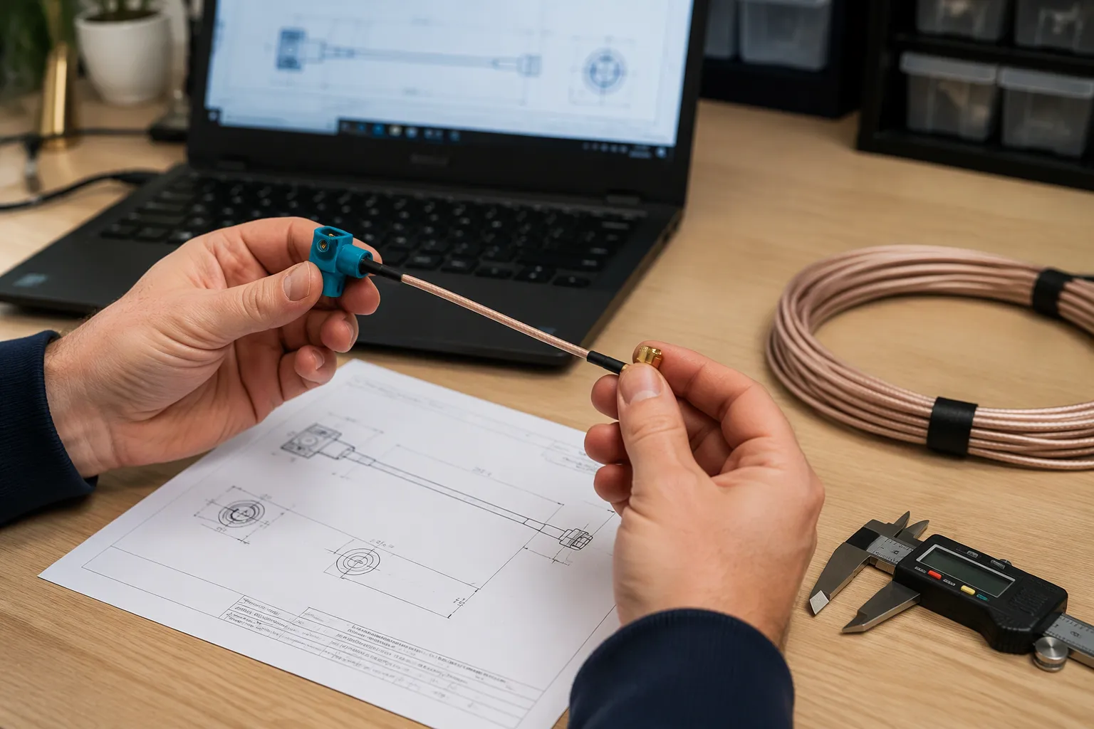
A standard assembly fits a standard route. Custom work begins when the vehicle layout departs from that baseline. Stantek notes that custom FAKRA assembly requirements arise when connector configuration, cable specifications, dimensions, termination, or installation conditions vary between applications. A non-standard length, a right-angle exit at a tight port, a sealed housing for an exterior gps antenna, or a specific pinout all justify a built-to-drawing part. YC Cable confirms that custom lengths and connector configurations accommodate vehicle routing and available installation space. The same supplier also builds FAKRA-to-SMA, FAKRA-to-SMB, and multi-port variants for navigation, telematics, and antenna programs.
Buyer Information to Provide LEADSIGN
A clear requirement package shortens every later step. Soarcable advises buyers to provide the application, both interfaces, a pin-to-pin requirement, lengths or mechanical dimensions, expected quantity, and the desired inspection or test evidence. Unknown items should go to engineering review rather than stay implied.
Requirement area | What to provide |
|---|---|
Application context | Vehicle system, function, and installation location |
Interfaces | Antenna and receiver port part numbers, gender, coding, keying |
Electrical definition | Pin-to-pin table, signal names, shielding and grounding approach |
Mechanical design | Length, bend limits, strain relief, jacket, labels |
Verification | Inspection, continuity, pinout, and functional checks |
Cable construction belongs in the same package. A short interior run may accept rg174, while a long roof-to-dash path needs lower-loss coax. State the shielding requirement and the straight or right-angle body at each end. Describe moisture, vibration, and temperature exposure. LEADSIGN offers OEM and ODM services for [custom automotive cable assemblies], and the team reviews each drawing before quoting.
Samples, Testing, and Lead Times
Samples lock the design before volume production. Wire Harness Production reports no minimum order quantity for samples or production, and sampling locks connector coding, cable construction, routing assumptions, and test scope. Typical checks include continuity, pin-map confirmation, shield continuity, connector retention, and visual inspection. Programs with tighter RF risk can add insertion-loss or return-loss validation through the customer or a qualified third party. Zomwave cites lead times of 4–6 weeks from ideal partners, with scalable order quantities from 100 units upward. Buyers should request a sample record and test report options with the quote. A gps antenna replacement project benefits from the same discipline: confirm the factory port, then specify the new assembly against it. Final lead times depend on complexity and appear in the quotation.
Three steps settle most selection work. First, confirm connector type and coding; FAKRA C is the common choice for GPS/Galileo feeds. Second, match cable loss and length to the system's signal budget. Airpluxtec notes that every interconnection point adds mismatch and loss, so connector integrity matters. Third, verify compliance and environmental fit.
The automotive GPS antenna cable is one part of a system. The gps antenna, receiver, routing, and installation all shape positioning performance. A quality gps antenna cannot rescue a poor route.
For a custom FAKRA GPS or GNSS assembly, contact LEADSIGN at info@leadsignauto.com or visit https://www.fakraconnectors.com. The team reviews each cable drawing before quoting.
FAQ
Which FAKRA code should a GPS or Galileo antenna cable use?
Code C is the common choice for GPS/Galileo antenna feeds. The mechanical key and housing color identify the coding. A Code C plug will not mate with a differently keyed jack. Buyers should confirm the receiver port before ordering, since Code D also appears depending on the application.
Does a FAKRA connector improve positioning accuracy on its own?
No. A FAKRA connector passes the signal with low reflection and holds the connection secure. Positioning performance depends on the antenna, receiver, satellite visibility, software, installation environment, and correction services. The connector protects signal integrity along the path, but it does not create accuracy.
When should an installer choose a FAKRA-to-SMA adapter instead of a native FAKRA cable?
A FAKRA-to-SMA adapter fits bench testing, aftermarket modules, and prototype hardware with SMA ports. Native FAKRA suits links that stay inside the production vehicle harness. Each adapter adds two extra interfaces, so installers should reserve adapters for legacy compatibility and test setups.
What causes a gps antenna to deliver an unstable fix after installation?
Common causes include a wrong connector coding, poor cable termination, damaged shielding, excessive cable length, poor grounding, and routing near noisy electronics. Moisture intrusion at an unsealed connector also degrades performance. Installers should test the as-built path and confirm the receiver interface and bias voltage.
How does a buyer specify a custom gps antenna cable assembly?
The buyer should provide both interface part numbers, connector type and coding, cable length and construction, shielding needs, pinout, straight or right-angle bodies, and environmental conditions. Samples and test scope should be agreed before volume production. LEADSIGN reviews each drawing before quoting.
See Also
Improve Your Car's Navigation System Using Fakra GPS Antennas
Advantages of Fakra GPS Connectors for Better Automotive Navigation Systems
Why GPS Antennas with Fakra Connectors Are Essential for Vehicles
Advantages of Using Car GPS Systems Equipped with Fakra Connectors