FAKRA Aerial Connector Guide for GPS, AM/FM and Cellular Antennas

FAKRA is a standardized 50 Ω automotive RF connection system. Its keyed housings, color identification, locking design, and broad product range make it suitable for demanding vehicle antenna systems. This guide explains how to choose FAKRA connections for GPS, broadcast radio, and cellular applications.
FAKRA Connectors in Automotive Antenna Systems
ISO 20860-1 defines a 50 Ω radio-frequency connection-system interface for road vehicles. Standard FAKRA products commonly operate from DC to 6 GHz, depending on the connector, cable, termination, and test setup.
The metal RF contact is based on an SMB-style interface. A plastic housing adds mechanical keying and a secure latch. The keying system helps prevent an AM/FM lead from being connected to a GPS or cellular port.
Common products combine 50 Ω impedance, DC–6 GHz capability, automotive temperature performance, locking features, and multiple mounting options. These are design baselines, not universal guarantees. Confirm the exact drawing and cable-assembly report.
Antenna service | Main purpose | Key selection concern |
|---|---|---|
GPS/GNSS | Positioning and timing | Low loss, active-antenna bias, correct GPS code |
AM/FM | Broadcast reception | Radio code, diversity, phantom-power support |
LTE/5G | Telematics and mobile data | High-band loss, MAIN/DIV/MIMO identification |
Satellite radio | Digital audio reception | Regional frequency and receiver compatibility |
Wi-Fi/Bluetooth | Local connectivity | Port assignment, routing, and EMI control |

FAKRA GPS Antenna Connector Selection
GPS and GNSS receivers work with extremely weak satellite signals. Every decibel of cable and connector loss reduces the signal margin available at the receiver.
Many automotive GPS antennas are active. A low-noise amplifier sits inside the antenna module. The receiver supplies DC power through the same coaxial cable. A damaged center contact can therefore interrupt both the RF signal and antenna power.
Signal blue Code C and heather violet Code H are commonly associated with GPS, navigation, and telematics. Some vehicle programs use different assignments. Treat the OEM wiring diagram as the final authority.
Before specifying a GPS antenna connector, confirm:
GPS-only or multi-constellation GNSS support
Passive or active antenna architecture
Required bias voltage and current
Target frequency bands
Maximum cable attenuation
FAKRA code at both ends
Straight or right-angle cable exit
Roof, dashboard, or telematics-unit location
Sealing and temperature requirements
Cable length needs particular attention. Small-diameter coax saves weight and space, but usually has higher attenuation. The final decision should follow the receiver link budget, not packaging preference alone.
When a GPS system fails, check antenna bias voltage, current draw, center-conductor continuity, shield continuity, and RF loss. A multimeter cannot identify excessive insertion loss or an impedance discontinuity.
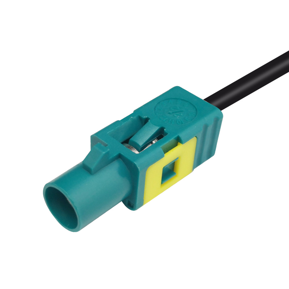
FAKRA Connector Options for AM/FM Antennas
AM/FM systems operate at lower frequencies than GPS and cellular links. However, the antenna architecture can still be complex. Vehicles may use amplified glass antennas, roof antennas, diversity receivers, or multiple antenna feeds.
Black Code A and cream-white Code B are commonly linked to radio applications. One may be assigned to a radio path without phantom supply, while another supports a powered antenna arrangement. Exact assignments can vary by regional standard and manufacturer.
This distinction matters after a head-unit replacement. A mechanically correct AM/FM antenna connector may deliver weak reception if the antenna amplifier receives no power.
Confirm the antenna amplifier, power path, diversity architecture, housing format, and the replacement unit's RF interface before selecting an adapter.
Avoid stacking several adapters behind the dashboard. Each added interface introduces loss and another possible loose connection. A single, application-specific assembly is usually more reliable.
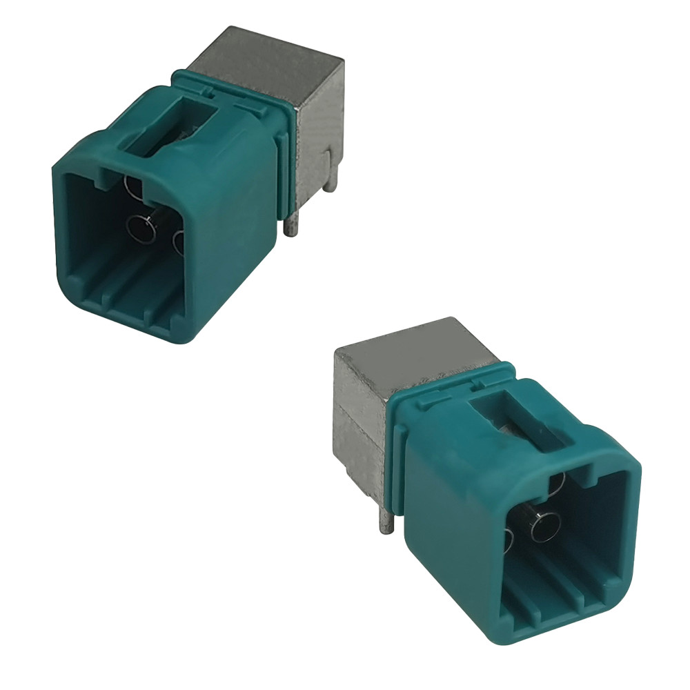
FAKRA Cellular Antenna Connectors for LTE, 5G and Telematics
Modern telematics systems may use several cellular antenna paths. A module can have MAIN, diversity, and MIMO ports, plus separate GNSS and Wi-Fi connections.
Bordeaux Code D is commonly associated with GSM or cellular service. Modern LTE and 5G platforms may use program-specific codes or multi-position housings. Identical-looking cables must still be connected to the correct modem port.
A cellular antenna connector must support the complete operating range. Cable loss increases with frequency. A cable that performs well at a low cellular band may consume too much margin at a higher band.
For LTE and 5G applications, specify:
Supported frequency bands
MAIN, DIV, or MIMO port assignment
Maximum insertion loss at the highest band
Return-loss requirement
Cable type, diameter, and finished length
Shielding effectiveness
Connector code and cavity position
Bend radius and routing restrictions
Required environmental validation
Port labeling should describe function, not simply “antenna.” Names such as LTE MAIN, LTE DIV, GNSS, and AM/FM reduce assembly errors and speed up troubleshooting.
Do not swap MIMO paths because their connectors share a color. The system may still connect to the network, but throughput and coverage can decline without an obvious fault code.
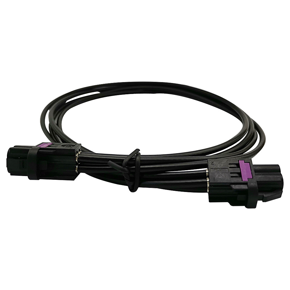
FAKRA Antenna Adapters and Automotive FAKRA Cable Assemblies
A FAKRA antenna adapter connects different RF interfaces or bridges an OEM harness to replacement equipment. Common combinations include FAKRA-to-SMA, FAKRA-to-SMB, FAKRA-to-DIN, and FAKRA-to-FAKRA extensions.
Typical adapter applications include:
Replacing an OEM radio or telematics unit
Connecting a test instrument to a vehicle antenna
Extending a GPS antenna lead
Moving an ECU or antenna module
Connecting prototype hardware to a production harness
Converting between an automotive and industrial RF interface
View LEADSIGN's FAKRA antenna adapter range for available interface combinations.
An adapter must preserve 50 Ω impedance through both interfaces. It must also match contact gender, not only housing terminology. Ask for a mating-face drawing when a supplier description is unclear.
The automotive FAKRA cable is equally important. Connector frequency ratings cannot compensate for a high-loss cable, poor crimp, or damaged shield.
Compare these cable-assembly parameters:
Parameter | Why it matters |
|---|---|
Cable impedance | A 50 Ω path limits reflections |
Attenuation | Determines signal loss at the target frequency |
Cable length | Longer cables create more insertion loss |
Shield construction | Controls EMI susceptibility and emissions |
Cable diameter | Must match the ferrule and rear seal |
Bend radius | Prevents impedance changes and shield damage |
Jacket material | Supports temperature, fluids, and abrasion requirements |
Termination process | Controls contact retention and RF consistency |
LEADSIGN's FAKRA coaxial cable category includes automotive coaxial and Mini FAKRA cable configurations.
Custom assemblies are valuable when standard leads do not match the application. Buyers can specify code, orientation, cable, length, sealing, labeling, and the connector at the opposite end. A qualified pre-terminated assembly also reduces variation from field crimping.
How to Select the Right FAKRA Connector
Start with the antenna service. Then confirm the electrical, mechanical, and environmental requirements as one controlled specification.
1. Identify the signal and frequency range
Document whether the path carries AM/FM, GPS/GNSS, cellular, satellite radio, or another RF service. For multi-band cellular links, use the highest operating frequency when checking cable loss.
2. Confirm 50 Ω impedance
FAKRA antenna systems normally use 50 Ω coaxial paths. The connector, cable, adapter, PCB transition, antenna, and receiver must share the same impedance environment.
3. Verify the mechanical code
Use the letter code and mating drawing. Color is helpful during assembly, but it is not a complete part specification. Neutral Z coding can mate with multiple standard codes, reducing mechanical error-proofing.
4. Check contact gender and orientation
Confirm both housing and center-contact gender. Select straight or right-angle construction based on cable routing, service access, and enclosure clearance.
5. Calculate cable loss
Use supplier attenuation data at the actual operating frequency. Multiply loss per unit length by the finished cable length. Add connector and adapter losses to the link budget.
6. Define the environment
Specify temperature, vibration, humidity, water, dust, fluids, and mating-cycle requirements. Exterior antenna connections may need matched interface seals and rear cable seals.
7. Validate the complete assembly
Continuity testing detects opens and shorts. It does not prove RF performance. Measure insertion loss and return loss over the required band. Repeat critical tests after vibration and temperature cycling.
Frequently Asked Questions
What is a FAKRA connector used for?
A FAKRA connector carries 50 Ω automotive RF signals. Common applications include GPS/GNSS, AM/FM radio, cellular telematics, satellite radio, Wi-Fi, Bluetooth, and some camera links. Mechanical keying and color identification help prevent incorrect connections inside vehicles.
Which FAKRA code is used for GPS antennas?
Code C in signal blue and Code H in heather violet are commonly associated with GPS, navigation, or telematics. Assignments can vary between regions and vehicle programs. Always verify the connector key and OEM drawing instead of selecting by color alone.
Can one FAKRA antenna adapter serve GPS, radio, and cellular systems?
Only when every electrical and mechanical requirement matches. Neutral Code Z can mate with several codes, but it does not make different antenna services interchangeable. Check frequency, loss, antenna power, contact gender, cable, and port assignment before using a universal adapter.
How does cable length affect a FAKRA antenna connection?
Longer coaxial cables create more insertion loss. The effect becomes more important at higher frequencies, especially in LTE and 5G systems. Calculate the complete link budget and measure the finished assembly rather than assuming a connector's frequency rating guarantees performance.
When should a custom FAKRA cable assembly be used?
Use a custom assembly when the application needs a specific code, length, cable, orientation, seal, label, or opposite-end connector. Pre-terminated assemblies also provide better control of stripping, crimping, shield termination, and RF testing than uncontrolled field assembly.
Build a Reliable Automotive Antenna Connection
FAKRA remains a central interface for automotive GPS, AM/FM, cellular, and telematics antenna systems. Its 50 Ω architecture, coding system, and secure locking design support reliable vehicle integration.
Successful selection still depends on the complete channel. Engineers must match the antenna service, frequency, code, cable loss, power arrangement, installation space, and environment. Procurement teams must lock those requirements into a controlled drawing.
LEADSIGN supplies FAKRA connectors, antenna adapters, and customized automotive cable assemblies for different antenna applications. Share your frequency bands, codes, cable type, length, orientation, sealing needs, and expected volume.
Contact LEADSIGN for a FAKRA antenna adapter or custom cable solution.

See also
Specifications vary by connector, cable, and vehicle program. Confirm current part drawings and validation reports before design release.