What Is an HSD Connector and Why It Matters for Automotive Instrument Clusters and Digital Displays

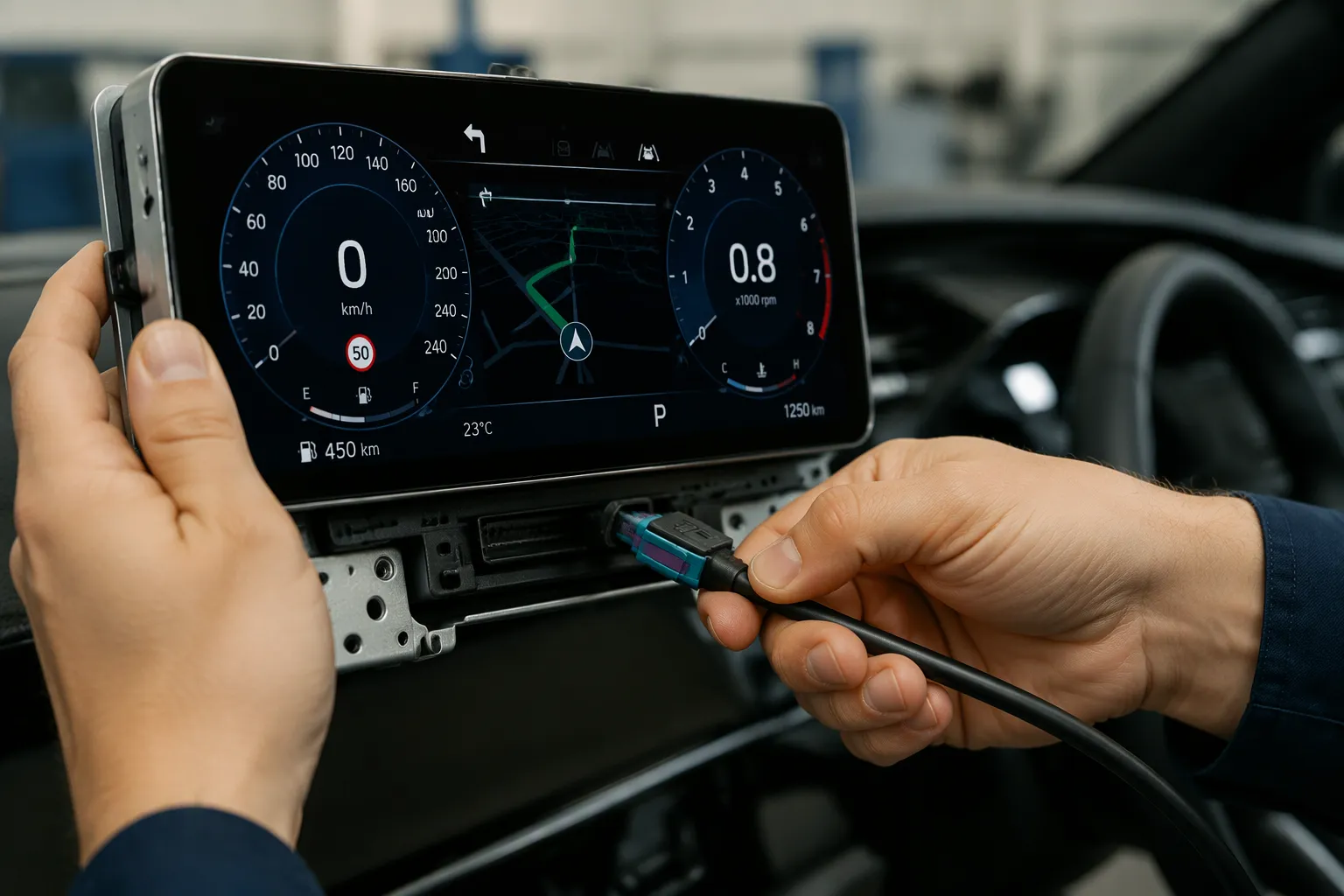
An HSD (High-Speed Data) connector is a shielded, impedance-controlled interface for high-speed data transmission in vehicles. It carries differential digital signals between displays, control units, and other electronic modules.
These connectors matter for instrument clusters and digital displays. They support reliable data links, add shielding against interference, fit compact spaces, and lock securely against vibration.
This guide connects HSD connector features to real cluster and display requirements.
Key Takeaways
An HSD connector is a shielded, impedance-controlled interface for high-speed data in vehicles.
HSD connectors keep digital displays and instrument clusters working reliably despite vibration and electrical noise.
Signal integrity depends on the whole cable assembly, not just the connector.
Choose the right connector coding, orientation, and cable length for your specific dashboard space.
Custom HSD assemblies solve unique routing and space challenges in vehicle designs.
What Is an HSD Connector?
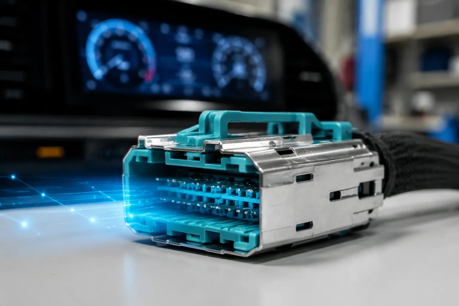
In Short: An HSD connector is a shielded, impedance-controlled interface for high-speed data in vehicles. It links displays, control units, and modules through differential signaling, secure locking, and keyed housings that prevent mismating.
Definition and Core Function
HSD stands for High-Speed Data. A high speed data (HSD) connector is a shielded, impedance-controlled, multi-contact interface built for differential digital data transmission in automotive applications. The automotive industry uses these parts wherever a vehicle must move large amounts of digital information between electronic modules.
The HSD connector family supports high-speed data transmission for display links, camera feeds, and module-to-module communication. Each unit carries a balanced signal pair inside a metal shield. This shielded, differential interconnect design rejects outside electrical noise and keeps the signal clean over the cable run. The shield and the balanced pair form one electrical system.
HSD connectors establish secure connections between electronic modules, displays, control units, and other vehicle systems. A cluster, a central screen, or a gateway module all rely on a stable link. The connector must hold that link through vibration, heat, and years of service. A loose or noisy connection can blank a display or corrupt a data frame.
An HSD connector is not a universal part for every automotive application. Compatibility depends on configuration, cable structure, pin assignment, impedance, shielding, termination, protocol, and validation. Two parts may share the HSD name and still differ in ways that block a working link. Engineers must confirm each of these items against the actual system.
Housing, Contacts, and Shielding
Six elements define a working HSD connector assembly.
Connector housing. The plastic body holds the contacts in position and provides the mating interface.
Contacts or terminals. Crimped metal terminals carry the differential signal and the ground path.
Shielding structure. A metal shell and ferrule surround the contacts and bond to the cable shield.
Cable. A controlled-impedance cable carries the signal pair and the shield.
Locking mechanism. Primary and secondary locks keep the connector seated under vibration.
Coding and keying features. Different codings on the plastic housing prevent mismating during assembly.
The housing and shielding work together. The shield blocks electromagnetic interference, and the housing keeps the contacts aligned. The locking mechanism adds retention force at the cable. Coding features stop an installer from plugging a connector into the wrong port. The metal shell also provides a ground path for the shield.
These parts serve automotive data transmission across many vehicle systems. High speed data connectors appear in infotainment units, driver-assist modules, and display control units. Each application sets its own demands on the assembly. An automotive high-speed connector must match the cable, the module port, and the validation plan.
HSD connectors also appear in camera links and sensor paths. HSD connectors in these roles carry high-speed data streams that drivers never see but always depend on. Engineers often compare HSD connectors by coding and cable exit. Buyers should treat the HSD connector as one part of a full cable assembly. The cable, the termination, and the validation plan all affect the final result. A correct connector on a mismatched cable still fails.
HSD Connector Applications in Digital Displays
Instrument Clusters and Infotainment Screens
Digital displays now fill the vehicle cabin. Engineers find hsd connectors in digital instrument clusters, central infotainment displays, rear-seat entertainment screens, head-up display systems, and driver information displays. The same parts link vehicle control modules, display control units, camera and video data links, LVDS display systems, and other high-speed data connections. Each application sets its own demands on the cable assembly.
The exact application depends on the system design and the specified cable assembly. A cluster link and a rear-seat screen link may use different pin assignments, cable lengths, and connector codings. Engineers must match the assembly to the actual module interface.
An instrument cluster is safety critical. The speedometer, warning lights, and indicators must work every time the vehicle starts. A failed link can blank the display or freeze a warning light. Serious issues can result on the road. Connection reliability matters more here than in any entertainment screen. The locking mechanism, shielding, and termination all carry real weight in this role.
HSD connectors may support high-speed data transmission for certain display and data links. The hsd connector automotive ethernet use depends on the specific configuration and validation. Buyers should confirm these application details before ordering:
Display type and resolution
Control module interface and pinout
Data or video protocol
Connector coding and gender
Cable length and routing path
Shielding and impedance requirements
Environmental conditions
Validation requirements
High Speed Data (HSD) Connector and Automotive Ethernet Links
Automotive ethernet carries high-speed audio, video, and data transmission across modern vehicles. The high speed data (hsd) connector family supports some of these links. Automotive ethernet connectors must match the cable, the impedance, and the termination plan. HSD connectors appear in many in-vehicle ethernet links, yet the name alone does not confirm compatibility.
Automotive ethernet links depend on the full assembly. The hsd connector automotive ethernet role varies by configuration and validation. Engineers should confirm the protocol, the pair arrangement, and the cable structure. They should also check the terminal displays and module ports on both ends. A correct hsd connector on a mismatched cable still fails. Final compatibility must be confirmed against the actual vehicle system, interface, pinout, drawing, and validation requirements.
Signal Integrity in Display Systems
Signal integrity decides whether a display shows a clean image or a corrupted one. A digital cluster must render the speedometer and warning lights without flicker, dropout, or frozen frames. Weak signal integrity produces exactly those faults. The link can pass a bench test and still fail in the vehicle once heat, vibration, and cable routing enter the picture.
Differential Signaling and Impedance Matching
Differential signaling sends one signal as two complementary voltages on a twisted pair. The receiver reads the difference between them, so noise that hits both wires cancels out. This scheme gives high-speed data links much of their noise immunity.
Impedance matching keeps that balance intact along the whole path. Certain high-speed display and data applications use 100-ohm differential systems, and engineers must confirm that value for the specific system rather than assume it. A mismatch at the connector termination reflects energy back toward the source. That reflection raises return loss and wastes part of the signal. Insertion loss measures the energy the cable absorbs over its run. Pair balance and cable geometry also shape the result. Skew between the two wires of a pair turns part of the signal into common-mode noise.
Shielding, Crosstalk, and Cable Length
Crosstalk occurs when one pair couples energy into a neighboring pair. Electromagnetic interference from motors, power cables, and nearby electronics adds another threat. Cable shielding and a bonded connector shell block much of this energy. Poor termination breaks the shield bond and opens a path for noise.
Cable length compounds every one of these effects. A longer run adds insertion loss and exposes more cable to interference. Hsd cable assemblies may serve certain LVDS display connections when the connector, cable, pin assignment, and electrical design all match. The name alone does not confirm LVDS compatibility. Hsd connectors and automotive ethernet links follow the same rule. The hsd connector automotive ethernet role depends on configuration and validation.
Customers should confirm these items for LVDS:
Display interface and control unit interface
Pinout and differential pair arrangement
Cable impedance and shielding
Connector coding
Cable length
Validation requirements
Engineers who treat signal integrity as a cable-assembly property, not a connector property, avoid most display faults. High-speed data transmission depends on the full path. Hsd connectors, cable, and termination form one system, and automotive ethernet links demand the same discipline.
HSD Connector Selection for Clusters and Displays
Coding, Keying, and Connector Orientation
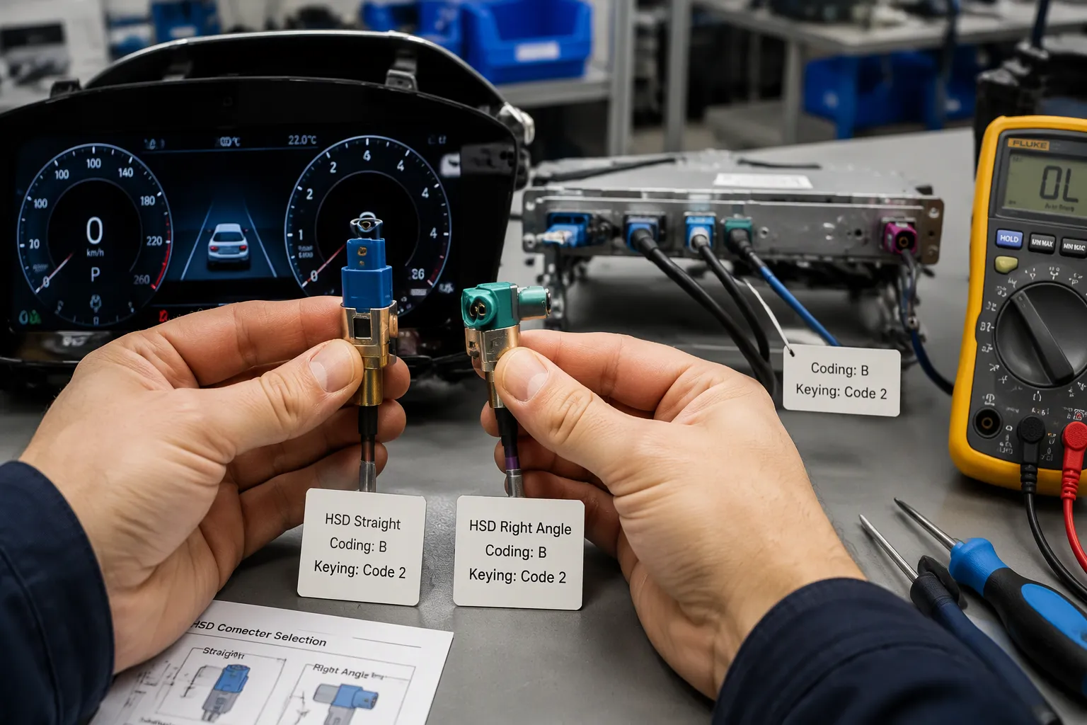
Coding and keying protect the assembly line and the service bay. Different codings on the plastic housing stop an installer from plugging a cable into the wrong port. Keying aligns the contacts before they touch, so bent terminals never reach the field. Both features help a technician match the correct vehicle display module on the first attempt. Production installation runs faster, serviceability improves, and wiring errors drop.
Buyers should confirm the housing, coding, keying, gender, mating interface, and pin assignment before ordering. These details decide whether the part mates at all. A connector that looks correct on a photo can still carry the wrong keyway.
Orientation matters just as much. A straight body sends the cable out along the mating axis. A right-angle hsd connector turns the exit ninety degrees. The right-angle hsd connector often solves a tight package behind a cluster, yet the correct choice depends on the vehicle design.
Selection point | Straight connector | Right-angle connector |
|---|---|---|
Available installation space | Needs axial room behind the port | Saves axial depth |
Cable exit direction | Straight back from the port | Turns along the housing |
Routing flexibility | Limited near a wall | Follows panels and brackets |
Clearance near brackets and panels | Can conflict with structure | Often clears nearby parts |
Connector access | Easy to grip in open space | Harder to reach in tight spots |
Mechanical strain | Cable pulls along the axis | Bend sits close to the body |
Ease of installation | Simple in open areas | Needs care during mating |
Compact cluster packaging | May not fit | Usually the better fit |
Cable Length, Routing, and Environmental Requirements
Correct length starts with the real routing path. Technicians measure around brackets and panels, not across open air. They add length for assembly and service movement, then remove excess slack. Tension at the connector damages the termination over time. Sharp bends and crushed sections harm the shield and the pair geometry. The minimum bend radius must be confirmed for the chosen cable. A moving display or dashboard assembly needs extra allowance. Routing away from interference sources protects high-speed data.
Automotive ethernet links and other high speed data (hsd) connector paths share these rules. The hsd connector automotive ethernet role depends on the full assembly, and automotive ethernet validation covers the cable run, not just the plug.
The vehicle environment adds mechanical and environmental stress. Vibration, temperature changes, mechanical movement, repeated installation, dust, moisture, bending, pulling, and long-term operation all act on the assembly. Buyers should confirm operating temperature, cable jacket material, shielding structure, locking mechanism, terminal design, environmental sealing, and validation requirements. An automotive high-speed connector must survive this duty cycle. Hsd connectors that pass a bench test can still fail in a hot, vibrating dashboard. Hsd connectors therefore need a validation plan tied to the actual mounting location. Engineers should treat every hsd connector as part of one system with the cable and the housing.
Standard vs. Custom HSD Cable Assemblies from LEADSIGN
When Standard Assemblies Fit
A standard HSD cable assembly suits a known display interface, a standard connector combination, and a fixed cable length. The routing path stays regular, and production repeats the same build. Buyers order against a published drawing and skip the design cycle. This path works well for common cluster and infotainment links.
When Custom Assemblies Are Needed
Custom work starts when the dashboard leaves little space or the two ends need different connector types. A straight-to-right-angle layout, special coding, or custom pin assignment also calls for a custom build. Prototype development, low-volume production, OEM integration, and aftermarket display installation often fall here. Multi-branch designs and special lengths add further reasons.
LEADSIGN supplies HSD connectors and HSD cable assemblies, including hsd lvds cables and hsd usb cable assemblies. The team supports cable length, connector configuration, interface matching, coding, and routing. Buyers can also source automotive high-speed data cables and high speed data assemblies for display links. For automotive ethernet runs, the hsd connector automotive ethernet role still depends on configuration and validation.
Specification | Why it matters | What the buyer should confirm |
|---|---|---|
Display application and type | Sets the interface and protocol | Cluster, center screen, or HUD |
Control module and protocol | Defines the data link | Module type and video protocol |
Connector family, gender, coding | Decides mating | Housing and keyway |
Pin assignment | Controls signal routing | Pair arrangement |
Cable type, length, shielding, impedance | Shapes signal quality | Drawing values |
Straight or right-angle, exit direction | Fits the package | Routing path |
Environmental conditions | Affects durability | Temperature and sealing |
Samples, drawings, validation | Proves the build | Test plan |
Quantity, packaging, delivery | Sets the order | Schedule |
Common selection mistakes include choosing by appearance, assuming every HSD connector supports the same protocol, and ignoring pin assignment. Others confuse gender, pick the wrong coding, or order the wrong length. Skipping the bend radius, routing near interference, and failing to confirm the module interface all cause rework. Buyers should request a drawing, test samples, and avoid forcing a mate or leaving tension at the connector.
Contact LEADSIGN for HSD connector information, display cable assemblies, custom design, drawings, samples, and quotations. Share the application, cluster type, module interface, pinout, coding, length, orientation, routing, environment, and quantity.
An HSD connector is a shielded, impedance-controlled interface that carries differential digital signals between vehicle modules. Its shielding, compact body, secure locking, and reliable high-speed data transmission keep instrument clusters and digital displays working under vibration and electrical noise.
The technical features covered earlier map directly to selection decisions. Engineers and buyers weigh coding, orientation, cable length, and signal integrity against each real dashboard package. Final compatibility still requires confirmation against the actual vehicle system, interface, pinout, drawing, and validation requirements.
HSD connectors continue to evolve. Designers of HSD connectors refine shielding and contact geometry to keep pace with higher-resolution displays and faster high-speed data rates.
FAQ
Do all HSD connectors work with every display system?
No. Compatibility depends on configuration, cable structure, pin assignment, impedance, shielding, termination, protocol, and validation. Two parts may share the HSD name and still fail to mate or carry the signal. Engineers should confirm each item against the actual module interface before ordering.
Can an HSD cable assembly carry an LVDS display signal?
Sometimes. Certain LVDS display systems accept an HSD cable assembly when the connector, cable, pin assignment, and electrical design all match. The name alone does not confirm LVDS compatibility. Buyers should verify the display interface, pinout, pair arrangement, impedance, shielding, and validation plan.
Why does connector coding matter in a cluster build?
Coding and keying stop an installer from plugging a cable into the wrong port. They align contacts before they touch and help technicians match the correct display module on the first attempt. Buyers should confirm housing, coding, keying, gender, mating interface, and pin assignment before ordering.
How does an engineer determine the right cable length?
The engineer measures the real routing path around brackets and panels, then adds allowance for assembly and service movement. The build should avoid excess slack, tension at the connector, sharp bends, and crushed sections. The minimum bend radius must be confirmed for the chosen cable.
When should a buyer request a custom HSD assembly?
Custom work fits special lengths, mixed connector types at each end, straight-to-right-angle layouts, special coding, custom pin assignments, multi-branch designs, prototypes, and low-volume builds. Standard hsd connectors suit known interfaces and fixed lengths. Buyers should share the application, pinout, routing, and validation needs with the supplier.
See Also
Why HSD Connectors Play a Critical Role in Automotive Manufacturing
Key Benefits of HSD Connectors for Automotive Infotainment Systems Today
Understanding the Fundamental Role of HSD Connectors in Automotive Applications
How HSD Connectors Deliver Major Benefits Across Automotive Systems
Why HSD Connectors Are Essential for Today's Modern Vehicles