Expert Advice on Maintaining PCB Board to Wire Connectors – Professional B2B Guide (2026)

Intro: Correct Maintenance Prevents Loose Connections, Corrosion, and System Failures
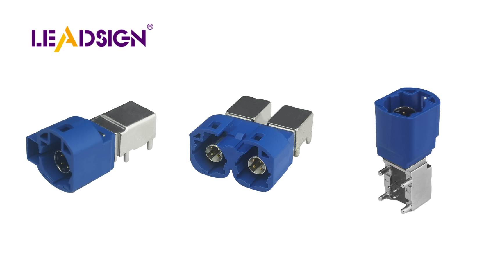
PCB board to wire connectors are the critical interfaces between a printed circuit board and external wiring – power, sensors, actuators, and communication lines. Neglecting their care leads to loose terminals, corrosion, increased resistance, and intermittent failures. Regular inspection, cleaning, and proper installation habits extend connector life and ensure reliable operation in demanding environments (automotive, industrial, medical). This guide provides best practices for installation, maintenance, troubleshooting, and replacement of PCB wire‑to‑board connectors. For high‑speed data applications (GPS, cameras, USB‑C), LEADSIGN offers pre‑terminated FAKRA and HSD cables that simplify PCB connectivity.
1. Best Practices for Installing PCB Board to Wire Connectors
✅ Pre‑Installation Preparation
Step | Action |
|---|---|
Select the right connector | Match connector type to application (vibration resistance for automotive, high‑speed data for cameras/USB). |
Verify compatibility | Ensure pin pitch, pin count, and footprint match your PCB layout. Check wire gauge compatibility (AWG). |
Inspect components | Look for bent pins, cracks, corrosion. Replace damaged parts before installation. |
Pro tip: For high‑speed data (GPS, camera, USB‑C), use pre‑terminated FAKRA or HSD cables from LEADSIGN – no field crimping, guaranteed impedance.
✅ Step‑by‑Step Installation
Align connector correctly – place connector over PCB footprint; ensure pins align with through‑holes or surface pads.
Apply gentle, even pressure – do not force. If resistance is felt, re‑check alignment. Forcing bends pins or cracks the housing.
Secure the connector – use screws, clips, or integrated locks (if present) to prevent loosening under vibration.
For crimp‑style wire‑to‑board: crimp terminals with ratcheting tool, perform pull test, then insert into housing.
✅ Tools You’ll Need
Tweezers or pick set (for fine pitch connectors)
Alignment jigs (for high‑pin‑count connectors)
Ratcheting crimper (with correct die)
Soldering iron (temperature‑controlled, for through‑hole connectors)
Safety glasses and gloves
Safety during soldering/crimping: Work in a well‑ventilated area. Wear eye protection. Avoid touching hot surfaces.
✅ Following Manufacturer Guidelines
Always read the datasheet – it contains electrical ratings, mechanical dimensions, and installation instructions.
Push‑in terminal block PCB connectors simplify installation: no soldering or crimping, quick wire insertion, secure spring clamp.
Advantages of push‑in terminal blocks:
Tool‑less, time‑saving
Accepts multiple wire gauges
Reliable under vibration
2. Maintaining PCB Connectors for Long Life
✅ Regular Inspection and Cleaning
What to check | What to look for | Action |
|---|---|---|
Physical damage | Cracked housing, bent pins, discolouration | Replace connector |
Corrosion | Green/white powder on metal surfaces | Clean with contact cleaner; replace if pitted |
Loose terminals | Wires move or connector wiggles | Re‑crimp or replace terminal |
Contamination | Dirt, dust, flux residue | Clean with PCB‑safe cleaner and soft brush |
Cleaning method: Use isopropyl alcohol or specialised PCB cleaner with a soft brush or lint‑free cloth. Do not use water or abrasive materials.
✅ Environmental Protection
Moisture: Apply conformal coating over the PCB around the connector (avoid inside connector). Use sealed connectors for wet environments (IP67/IP69K).
Heat: Ensure connectors are rated for the maximum operating temperature (engine bay: -40°C to +125°C).
Dirt / dust: Use dust caps when connectors are unmated.
✅ Lubrication and Tightening
Apply dielectric grease to rubber seals (not to electrical contacts) to prevent moisture ingress.
Periodically tighten screws or retaining clips – especially in high‑vibration applications (vehicles, industrial machinery).
Push‑in terminal blocks require no tightening – but inspect for wire retention.
3. Replacing Old or Damaged Connectors
🔹 When to Replace
Bent or broken pins
Cracked or melted housing
Severe corrosion that does not clean off
Intermittent connection after cleaning and tightening
Loose retention (connector no longer clicks or locks)
🔹 Safe Replacement Procedure
Turn off power – disconnect battery or unplug the device.
Document wiring – label wires or take photos for correct reconnection.
Remove old connector – use a depinning tool or gently unscrew. Do not pull by wires.
Clean PCB pads – remove old solder (if through‑hole) or clean surface pads with isopropyl alcohol.
Install new connector – align carefully, press gently, secure with screws/locks.
Test – power on, verify function, check for continuity and voltage drop.
For pre‑terminated data cables (FAKRA, HSD): Replace the entire cable assembly – do not attempt to re‑terminate.
4. Common Mistakes to Avoid
Mistake | Consequence | Prevention |
|---|---|---|
Forcing misaligned connector | Bent pins, cracked housing | Stop and re‑align |
Using wrong wire gauge | Loose connection, overheating | Match terminal to AWG |
Skipping regular inspection | Hidden corrosion → eventual failure | Schedule 6‑month checks |
Ignoring environmental protection | Moisture ingress, corrosion | Use sealed connectors or conformal coating |
Not following datasheet | Electrical or mechanical mismatch | Read manufacturer guidelines |
5. Troubleshooting PCB Board to Wire Connector Problems
Problem | Likely cause | Fix |
|---|---|---|
Intermittent connection | Loose terminal, poor crimp, fretting corrosion | Reseat connector; re‑crimp; clean contacts |
No power / signal | Broken wire, pushed‑back pin, open circuit | Check continuity; replace terminal or connector |
Corrosion (visible) | Water ingress, unsealed environment | Clean with contact cleaner; replace if severe; use sealed connector |
Overheating / melting | High resistance (corrosion or loose connection) | Replace connector; find root cause (undersized wire) |
Data signal loss (camera, GPS) | Using power connector for data or faulty FAKRA/HSD cable | Use FAKRA/HSD; replace pre‑terminated cable |
When to call a professional: If the PCB itself is damaged (lifted pads, burnt traces) or if the problem persists after connector replacement, seek expert repair.
6. Why LEADSIGN – For PCB High‑Speed Data Connectivity
For traditional power and signal wire‑to‑board connectors, many brands (TE, Molex, JST) offer excellent products. However, for high‑speed data (GPS, backup camera, 5G, USB‑C, Ethernet), LEADSIGN provides pre‑terminated FAKRA and HSD cables that plug directly into PCB‑mount versions of these connectors.
What LEADSIGN offers:
✅ FAKRA (standard & Mini) – all 14 colours, 50Ω, up to 20 GHz, IP67 optional
✅ HSD (USB‑C, Ethernet, LVDS) – 100Ω, locking, up to 5 Gbps
✅ Pre‑terminated cables – any length 0.3m – 20m, no field crimping
✅ Low‑loss, double‑shielded coax – for long runs and EV environments
✅ Bulk pricing – for shops, fleets, and distributors
For your business: When designing or repairing a PCB with GPS, camera, or USB‑C inputs, use LEADSIGN pre‑terminated FAKRA/HSD cables – they connect directly to the PCB‑mount connector, eliminating termination errors and saving labour.
Final Recommendations – Maintenance Checklist
Task | Frequency | Action |
|---|---|---|
Visual inspection | Every 6 months | Look for corrosion, bent pins, cracked housing. |
Clean with PCB cleaner | Annually or after contamination | Soft brush and cleaner; no water. |
Tighten screws / clips | Every service | For screw‑type terminal blocks. |
Apply dielectric grease | Annually | Only to rubber seals – not contacts. |
Replace damaged connectors | Immediately | Any bent pin, melt, or deep corrosion. |
For FAKRA/HSD data lines | As needed | Replace pre‑terminated LEADSIGN cable. |
Remember: A well‑maintained PCB connector ensures reliable power and signal transmission for the life of the equipment. Invest a few minutes in preventative care – it saves hours of troubleshooting.
Ready to simplify your PCB high‑speed data connections with pre‑terminated cables?
[Request a free LEADSIGN FAKRA/HSD sample kit] | [Get bulk pricing for pre‑terminated cables]
See Also
Improving Data Transfer Using FAKRA PCB Connectors
Advantages of FAKRA Connectors for Automotive PCB Use
Key Benefits of FAKRA PCB Connectors in Vehicles