Master the Installation of PCB Board Wire Connectors

Learning to install pcb board to wire connectors is very important. It helps make strong and lasting electronic connections. This skill keeps your projects working well for a long time. Good installation improves device performance and shows professional work. Ray PCB, an expert in PCB connectors, says:
"Thinking about electrical, mechanical, and assembly needs makes strong connectors that last."
By being precise and careful, you can make connections that last long and work well with modern electronics.
Key Takeaways
Proper installation of PCB wire connectors is crucial for creating strong and lasting electronic connections, enhancing device performance.
Gather essential tools like wire strippers, crimping tools, and screwdrivers to ensure accurate and secure connections.
Prepare wires by measuring, cutting, and stripping them correctly to avoid damage and ensure a snug fit in connectors.
Use the right die on your crimping tool to create a solid connection without damaging the wire or pin.
Always check the alignment of pins and connectors with the PCB to prevent misfits that could lead to device issues.
Regularly test connections with a multimeter to ensure they are functioning properly and to catch any faults early.
Practice and attention to detail in each step of the installation process will lead to improved skills and more reliable electronic systems.
Tools and Materials for Installing PCB Board to Wire Connectors
To install PCB wire connectors, you need proper tools and materials. These items help make your connections strong and accurate. Below is a simple guide to gather what you need.
Important Tools
Wire stripper
A wire stripper removes the plastic coating from wires. It shows the metal inside without breaking the strands. Pick a wire stripper that fits your wire size for neat results.
Crimping tool
Crimping tools attach wires to connector pins tightly. They press firmly to make a secure connection. Use crimping tools made for your connector type for best results.
Screwdriver (if needed)
Some connectors use screws to stay in place. A screwdriver tightens these screws so they don’t move. Keep different screwdrivers ready for various screw sizes.
Multimeter (optional)
A multimeter checks if your connections work properly. It ensures the wires and board are connected well. This tool isn’t required but adds extra safety.
Needed Materials
PCB board
The PCB board holds all your connections together. Make sure it’s clean and not damaged before starting work.
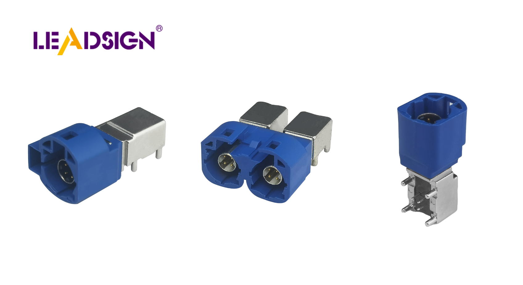
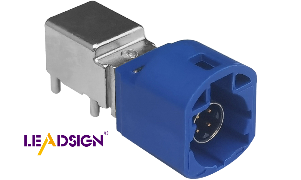
Wire-to-board connectors
These connectors join wires to the PCB securely. They are tough and last long with proper use. Choose ones that fit your project needs perfectly.
Wires (right size)
Wires of correct thickness are important for good connections. The size decides how much current they can handle safely. Match them with your PCB and connector requirements.
Connector pins or terminals
Pins or terminals hold wires inside the connectors firmly in place. They keep electrical flow steady between parts. Have enough pins or terminals ready for your project.
By gathering these tools and materials, you’re ready to start easily. Each item helps make strong, lasting wire-to-board connections.
Getting Ready for PCB Board to Wire Connectors
Good preparation makes installation easy and successful. Follow these steps to make strong connections that improve your electronic projects.
Getting the Wires Ready
Measure and cut wires to the right length.
First, figure out how long the wire should be. Use a ruler or tape measure to check the length. Cut the wire carefully to avoid extra slack or tightness. A clean cut helps with later steps.
Remove insulation to show enough metal wire.
Take a wire stripper and peel off the plastic covering at the ends. Only uncover enough metal to fit into the connector pin snugly. Don’t strip too much, as it can cause damage or short circuits. Keep all strands together without fraying them. You can use ferrules for extra protection against fraying.
Setting Up Your Crimping Tool
Pick the right die for your connector pin size.
Choose a die on your crimping tool that matches your connector pin size exactly. The correct die ensures a solid connection without damaging anything.
Adjust tool settings if needed.
Check if your crimping tool needs adjustments before you start using it. Some tools let you change pressure or alignment for better results. Proper settings help create a tight and secure crimp, which is important for good electrical flow.
By preparing wires well and setting up tools correctly, you ensure success in installation. These steps make connections stronger and last longer, even in tough conditions like high voltage or moving parts.
Step-by-Step Guide to Connect Wires to PCB Board
Putting the Wire into the Connector Pin
Line up the wire with the connector pin.
Hold the wire and pin in your hands. Make sure the metal part of the wire matches up with the hole in the pin. This step helps avoid mistakes later.
Push all wire strands fully into the pin.
Gently push the wire into the pin until it fits inside. Check that no strands are sticking out. This makes a strong connection and stops problems like loose wires.
Securing with a Crimping Tool
Place the pin with wire into crimping tool slot.
Put the pin, now holding the wire, into your crimping tool. Match it to the correct size slot on your tool for a good fit.
Squeeze handles tightly to lock wire in place.
Press down hard on your crimping tool handles. Keep squeezing until you finish crimping. The pin should hold onto the wire firmly without gaps or loose ends.
Adding Pin to Connector Housing
Slide crimped pin into its spot in housing.
Take your finished pin and slide it carefully into its housing slot. Push it gently but firmly until it sits properly inside.
Listen for click sound; check if secure.
You’ll hear a click when it locks in place. Gently pull on the wire to make sure it doesn’t come out. A tight fit means everything is ready for use.
By following these easy steps, you can connect wires securely to PCB boards. Each step helps create strong connections that work well and last long!
Connecting the Connector to the PCB
Match the connector with the PCB header or slot.
Find the correct spot on your PCB for the connector. Check if its shape and pins match the header or slot. Hold the connector firmly and place it above the header or slot. Make sure all pins line up with holes on the PCB. If they don’t match, it might cause damage or bad connections. Be careful and take your time to get it right.
Push in the connector or use screws if needed.
After aligning, press down gently but firmly on the connector. Use both hands to apply even pressure without tilting it. You’ll feel resistance as pins connect with the PCB. Keep pressing until it sits flat against the board. If screws are needed, use a screwdriver to tighten them evenly. This keeps everything secure without damaging parts. Once done, check that everything is steady and properly connected.
By attaching your connector carefully, you finish this step well. A good connection helps your project work smoothly and reliably.
Troubleshooting PCB Board to Wire Connectors
Common Problems
Loose wires or pins not fitting right
Loose wires happen when they aren't pushed in fully. Pins that don’t fit properly can stop the connector from sitting right. These problems may cause bad electrical flow and device issues.
Wires or covers damaged during stripping
Stripping wires wrong can break strands or tear covers. This makes connections weak and risks short circuits. Taking off too much cover shows too much wire, while too little leaves not enough metal for a good hold.
Fixes
Re-crimp loose wires and check alignment
To fix loose wires, take them out and look closely. Use the right tool size to crimp them again tightly. Make sure all strands are inside the pin before crimping. When placing the connector on the board, line up pins carefully with slots. Press firmly so it stays in place.
Test connections with a multimeter for faults
A multimeter checks if your connections work well. Set it to test continuity and touch probes to both ends of the connection. A beep means it’s working fine. If there’s no sound, check for broken parts or bad fits. Strip or crimp again if needed to fix it.
"Fixing problems keeps connections strong and projects lasting longer."
By solving these issues, you ensure your PCB wire connections stay reliable and strong.
Learning to install pcb board to wire connectors takes practice and care. Follow the steps in this guide closely. You will learn to prepare wires, use tools well, and make secure connections. Each step helps you improve your skills for better results. Practicing often makes you more confident and skilled. Always aim for accuracy and proper fit for strong connections. With effort, you can build reliable electronic systems that work great every time.
FAQ
What are PCB board wire connectors for?
PCB wire connectors join wires to circuit boards securely. They are used in cars, gadgets, and machines. These connectors help send power and data reliably.
Why is installing PCB connectors correctly important?
Proper installation makes connections last longer and work better. It stops loose wires, misaligned parts, and damage. Good connections prevent problems and save repair costs.
"Installing PCB connectors properly keeps them reliable." – Manufacturer Guidelines
How do I pick the right wire-to-board connector?
Choose a connector that fits your project needs. Look at pin size, spacing, current limits, and board fit. Check the manufacturer’s guide for exact details.
What tools do I need to install PCB connectors?
You’ll need a wire stripper, crimping tool, and maybe a screwdriver. A multimeter can check if connections work but isn’t required.
Can I ask the PCB maker for help during design?
Yes! Working with the maker early saves time and money later. They can suggest changes before production starts.
"Smart engineers work with makers early to improve designs."
How does automation help with PCB assembly?
Automation avoids mistakes by humans and makes circuits accurate. This improves performance while lowering repair costs over time.
"Automated PCBs perform better with fewer errors."
What if my connection doesn’t work?
Look closely at the connection first. Check for loose wires or broken parts. Use a multimeter to test it. If needed, re-strip the wire or fix alignment issues.
How do I avoid damage when stripping wires?
Use the right tool for your wire size. Strip only enough plastic so metal shows without breaking strands or exposing too much.
Why follow installation rules?
Following steps ensures strong connections that last long. It also speeds up setting up new projects by reducing mistakes or fixes needed.
"Good installation saves time when starting new projects."
How can I test if my connections are good?
Use a multimeter to check continuity between two points. A beep means it’s working fine! Regular checks keep your connections reliable.
See Also
An In-Depth Overview of HSD Connectors
Advantages of FAKRA Connectors for PCB in Vehicles
Significance of FAKRA PCB Connectors for Vehicle Communication