Expert Advice on Identifying and Replacing Automotive Plugs and Connectors – Professional B2B Guide (2026)

Intro: A Bad Connector Can Disable a Whole System
Automotive plugs and connectors are the workhorses of your vehicle’s electrical system. When one fails, you may experience flickering lights, intermittent sensors, or even a no‑start condition. The good news: identifying and replacing a faulty connector is a straightforward process with the right tools and knowledge. For repair shops and fleet managers, mastering this skill reduces diagnostic time and prevents comebacks.
In this guide, you will learn:
How to spot a bad connector (symptoms, visual signs)
How to test with a multimeter
Step‑by‑step replacement procedure
How to choose the right replacement connector
Why LEADSIGN pre‑terminated FAKRA/HSD cables simplify data connector repairs
1. How to Spot a Bad Automotive Connector
Symptom | What it indicates |
|---|---|
Flickering lights / intermittent operation | Loose terminal, poor crimp, or corroded contact. |
Burnt smell or melted plastic | Overheating due to high resistance (loose connection or overload). |
Green/white powder on terminals | Corrosion from moisture ingress – common on unsealed connectors. |
Device works sometimes but not always | Intermittent open or high resistance – often a loose lock. |
Visible cracks or bent pins | Physical damage – replace immediately. |
Pro tip: If a system acts erratically (e.g., a backup camera works then fails), wiggle the connector while monitoring the device. If the device responds, the connector is the problem.
2. Testing with a Multimeter – A Quick Guide
A multimeter is your best friend for diagnosing connector issues.
Test | Setting | Procedure | Pass / Fail |
|---|---|---|---|
Continuity | Ohms (Ω) or beep mode | Probe from one end of the wire to the other (through the connector). | Beep = good; no beep = open circuit. |
Voltage drop | DC volts | Probe on both sides of the connector while circuit is powered. | <0.2V = good; higher = resistance in connector. |
Resistance to ground | Ohms (Ω) | Probe pin to chassis ground (with circuit off). | >1 MΩ = good; lower = short to ground. |
For FAKRA / HSD data connectors: A continuity test is not enough – impedance mismatch can still ruin signal. Use pre‑terminated LEADSIGN cables to avoid field testing.
3. Visual Inspection – What to Look For
Corrosion: Green, white, or blue powder on metal terminals.
Loose pins: Gently tug each wire – it should not move.
Melted plastic: Indicates overheating; replace connector and find root cause (undersized wire, overload).
Cracked housing: Water ingress will follow; replace.
Bent or pushed‑back pins: Straighten carefully with a pick tool; if loose, replace terminal.
Common corrosion causes: Unsealed connectors in engine bay or underbody. Always replace with sealed (IP67) connectors in those locations.
4. Tools & Supplies You Will Need
Tool | Purpose |
|---|---|
Multimeter | Testing continuity, voltage drop, resistance |
Ratcheting crimper (with interchangeable dies) | Attaching new terminals |
Wire strippers | Removing insulation without nicking strands |
Pick / depinning tool | Removing terminals from connector housing |
Heat gun | Shrinking heat‑shrink tubing |
Dielectric grease | Sealing and corrosion protection (on seals only) |
Contact cleaner | Cleaning terminals |
Replacement connector & terminals | Match original (or upgraded sealed version) |
Safety first: Disconnect battery (negative terminal) before any work. Wear safety glasses.
5. Step‑by‑Step Replacement Procedure
✅ Step 1: Remove the Old Connector
Disconnect battery negative terminal.
Locate the faulty connector.
Use a depinning tool to release terminals from the housing (or cut the wires if you plan to replace the whole pigtail).
Remove the connector.
✅ Step 2: Inspect Wires & Adjacent Components
Look for damaged insulation, burnt wires, or corrosion extending beyond the connector.
Cut back to clean, uncorroded copper.
If the wire is too short, splice in an extension with heat‑shrink butt connector.
✅ Step 3: Prepare Wires for New Connector
Strip 5‑8 mm of insulation – do not nick strands.
Slide heat‑shrink tubing (adhesive‑lined) onto the wire if using.
✅ Step 4: Terminate – Crimp or Solder
Crimping (preferred for automotive): Use ratcheting crimper with correct die. Pull test (5‑10 lbs).
Soldering (only for low‑vibration interior): Heat wire and terminal, apply solder, let cool without movement.
✅ Step 5: Insert Terminals into New Housing
Push each terminal into the correct cavity until it clicks.
Gently tug to ensure retention.
If connector has a secondary lock (CPA), engage it.
✅ Step 6: Seal & Protect
Apply dielectric grease to rubber seals and grommets – not to electrical contacts.
Slide heat‑shrink tubing over the crimp/splice and heat to seal.
For exterior connectors, use heat‑shrink butt connectors or sealed housings.
✅ Step 7: Test Before Final Assembly
Reconnect battery (negative last).
Operate the circuit (light, sensor, camera) – confirm function.
Use multimeter to verify voltage drop and continuity.
✅ Step 8: Secure & Strain Relief
Zip‑tie the wire within 5‑10 cm of the connector back.
Route wires away from sharp edges, heat, and moving parts.
6. Choosing the Right Replacement Connector
Factor | What to check |
|---|---|
Connector shape & keying | Must match the mating connector (round, rectangular, colour‑coded). |
Pin count | Count the cavities – one extra or missing will not fit. |
Sealing requirement | Use IP67 for exterior/underbody; unsealed for interior. |
Wire gauge (AWG) | Match terminal size to wire (red=22‑18, blue=16‑14, yellow=12‑10). |
Current rating | Must handle circuit load (e.g., 10A for lights, 3A for sensors). |
Data capability | For video/GPS → FAKRA 50Ω; for USB/Ethernet → HSD 100Ω. |
OEM vs. aftermarket: OEM connectors guarantee fit. High‑quality aftermarket (e.g., LEADSIGN for FAKRA/HSD) can be equivalent at lower cost. Avoid generic unbranded connectors.
7. Why LEADSIGN for Data Connector Replacement
For power connectors (Deutsch, Weather Pack, Molex), many brands are available. But for high‑speed data (FAKRA, HSD), field replacement is difficult – crimping requires expensive tooling and skill.
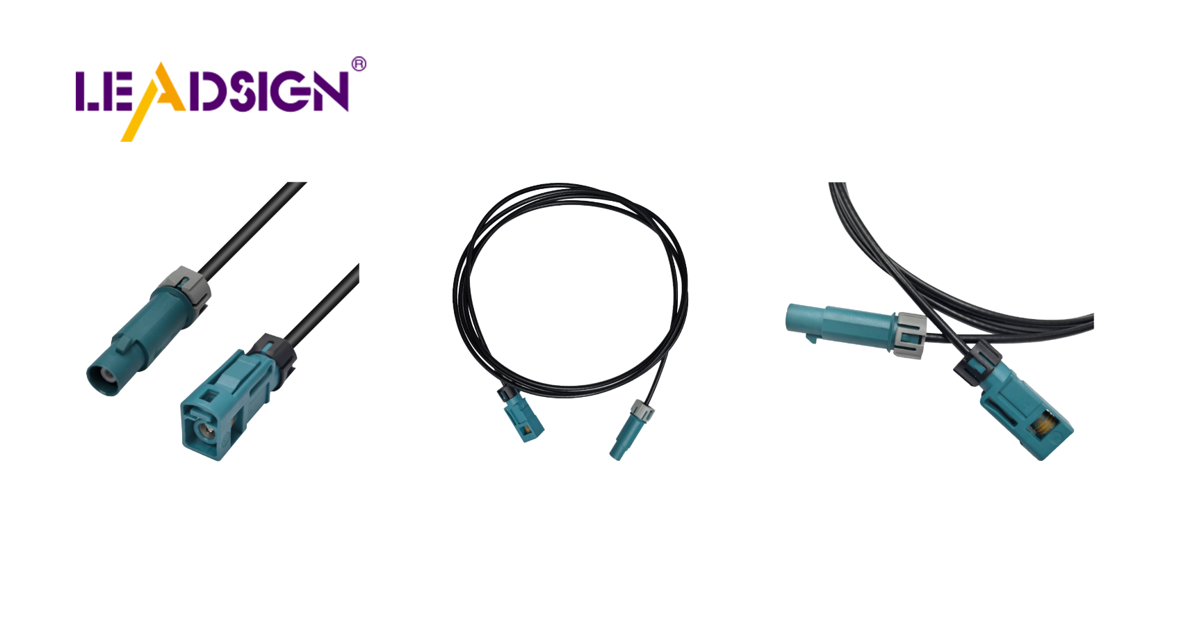
LEADSIGN pre‑terminated cables eliminate these problems:
✅ FAKRA (standard & Mini) – all 14 colours, 50Ω, up to 20 GHz, IP67 optional
✅ HSD (USB‑C, Ethernet, LVDS) – 100Ω, locking, up to 5 Gbps
✅ Pre‑terminated – ready to install – no crimping, no impedance mismatch
✅ Custom lengths 0.3m – 20m
✅ Bulk pricing for shops and fleets
When a camera or GPS connector fails, replace the entire LEADSIGN cable – not just the plug.
Final Recommendations – Connector Replacement Checklist
Step | Action |
|---|---|
☐ | Disconnect battery (negative first) |
☐ | Inspect and diagnose (visual + multimeter) |
☐ | Cut & prepare wires to clean copper |
☐ | Select correct replacement connector (sealed/unsealed, pin count, gauge) |
☐ | Crimp or solder terminals; pull test |
☐ | Insert into housing; engage secondary lock |
☐ | Apply dielectric grease to seals only |
☐ | Heat‑shrink for moisture seal |
☐ | Test circuit (power on, check function) |
☐ | Secure harness with zip‑ties |
Remember: A properly replaced connector will outlast the vehicle. A rushed or incorrect replacement will come back to haunt you.
Ready to simplify data connector repairs with pre‑terminated cables?
See Also
Enhancing Data Transfer in Vehicles With Superior Connectors
A Comprehensive Overview of Ford Fakra Connectors
Why FAKRA Connectors Are Crucial for Automotive Use