Exploring High-Speed PCB Design for Automotive Wire Applications

High-Speed PCB Design is important for cars. It helps send data fast and supports new tech like cameras and USBs. Cars face special problems. Engineers must think about temperature changes, shaking, and signal interference. These issues need strong design plans to keep working well. Solving these problems makes car tech better and safer.
Understanding High-Speed PCB Design
High-Speed PCB Design is key in today's car systems. Engineers focus on certain features for good data flow and system trust.
Defining High-Speed PCB Characteristics
Signal Integrity and Power Integrity
Signal integrity means signals move without getting messed up. Engineers make PCBs to keep signals clear, which is important for correct data. Power integrity means steady power to parts. Both are crucial to stop mistakes and keep things working well.
Minimizing EMI/EMC Issues
Electromagnetic interference (EMI) and electromagnetic compatibility (EMC) can mess up electronics. Engineers use special design tricks to cut these problems. Shielding and grounding help lower interference, making sure car systems work right.
Key Parameters for High-Speed Design
Maximum Frequency and Data Transfer Rate
High-Speed PCB needs focus on frequency and data speed. Engineers pick materials that handle high frequencies. This makes fast data transfer possible, needed for cameras and entertainment systems.
Component and Routing Density
Component density means how many parts fit on a board. High-Speed PCB uses tight layouts to save room. Routing density is about paths connecting parts. Engineers plan these paths carefully to stop signal loss, boosting system performance.
Design Considerations for Cars
Transmission Line Design and Signal Control
Making Connections as Lines
Engineers see connections as lines to keep signals good. They plan the layout so signals move well. Good design stops disruptions, which helps data move right in cars.
Stopping Signal Errors
Signal bouncing can cause mistakes. Engineers use tricks like matching to stop this. By planning the board well, they cut signal losses, keeping parts talking clearly.
Picking Materials and Controlling Impedance
Why Material Matters
Material affects how fast and clear signals are. Engineers pick materials with the right properties for best performance. This choice keeps signals strong, especially at high speeds.
Using Pair Signals
Pair signaling cuts noise and makes data better. Engineers use this to boost signal strength. Sending in pairs gives better results, needed for car electronics today.
Practical Uses and Connector Choices
HSD Connectors in Cars
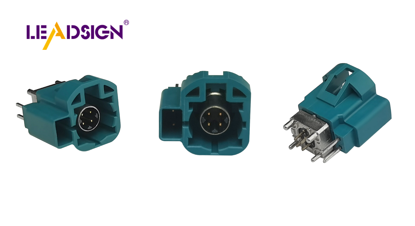
Flexible and Reliable Data Sending
HSD connectors are key in car electronics. They work with things like cameras and USBs. These connectors send data reliably, which is important for new cars. Engineers pick them for handling fast data well. HSD connectors are key
Following Rules and Standards
HSD connectors meet strict car rules. They follow safety protocols. Engineers trust these connectors to keep systems working right. Meeting standards ensures they fit with other parts.
Picking the Right PCB Connectors
Voltage and Current Needs
Choosing PCB connectors means knowing voltage needs. Engineers check if connectors handle system power demands. Right choices stop overheating and keep things stable.
Issues with Many Connections
Many connections can be tricky. Engineers design layouts for lots of connections without problems. They save space while keeping signals clear. This planning boosts car system efficiency.
Tools and Techniques for Better PCB Layouts
How CAD Software Helps in PCB Design
CAD software is important for making PCBs. Engineers use it to make exact layouts. It helps them see and plan the board before building.
Testing and Improving Layouts
Engineers use CAD to test PCB designs. This lets them try different setups and find problems. They can make layouts better for good performance. The software lets them try ideas without real models.
Simulation Benefits:
Finds signal issues
Checks power networks
Looks at heat plans
Predicting Design Effects and Tolerances
Knowing how a PCB works in real life is key. CAD helps engineers guess design effects. It lets them adjust for building limits, so the product fits needs.
Key Predictions:
How parts affect signals
Trace width and spacing effects
Material impact on speed
Using CAD, engineers improve designs for fast car tech. This saves time and makes products work well and last longer.
High-speed PCB design is key for cars. It helps send data well and supports tech like cameras and USBs. Engineers deal with problems like temperature changes and signal issues. They need strong plans to fix these.
Future PCB trends bring cool new ideas. Engineers will try new materials to improve how things work. As car tech grows, high-speed PCBs will keep making cars smarter and safer.
See Also
Maximizing Automotive Data Transfer with FAKRA PCB Connectors
The Benefits of FAKRA PCB Connectors for Automotive Use
The Pros of FAKRA PCB Connectors in Automotive Usage
Improving Automotive Data Transfer: Enhanced Connectors and Cables