Easy steps to connect pcb board to wire connectors

Connecting wires to a PCB board using pcb board to wire connectors is easy. These connectors make it simple to link wires and the PCB. They are strong and easy to use, even if unplugged often. Their design allows many connections in small spaces. They reduce electronic noise, improving how devices work. Using proper tools helps you connect wires smoothly and reliably.
Key Takeaways
Use the right tools, such as wire strippers and crimping tools, to ensure strong and reliable connections.
Prepare wires by cutting them to size and removing insulation carefully to avoid damage.
Choose quality wire-to-board connectors that fit your PCB and wire size for optimal performance.
Crimp wires tightly to create secure connections, and always check for proper alignment before attaching to the PCB.
Test your connections with a multimeter to ensure they are functioning correctly and avoid future issues.
Avoid common mistakes like stripping too much insulation or using the wrong tools to ensure lasting connections.
Regularly inspect and clean your tools to maintain their effectiveness and prolong their lifespan.
Tools and Materials Needed

To connect wires to a PCB, you need the right tools. These tools and materials make the process easy and reliable.
Important Tools
Using proper tools helps create strong wire connections. They also improve how well your work turns out.
Wire stripper: This tool removes plastic coating from wires. It keeps the metal inside safe for clean connections.
Crimping tool: A crimping tool attaches terminals to wires tightly. It makes strong electrical and physical bonds.
Soldering iron (optional): Some connectors may need soldering. This tool melts solder to join wires to parts of the PCB.
Multimeter: A multimeter checks if your connection works properly. It ensures everything is secure and working as it should.
Tip: Clean your soldering iron with a wet sponge often. This stops dirt buildup, helping you make better joints.
Materials
Good materials help your connections last longer and work better. Choose quality items for fewer problems later.
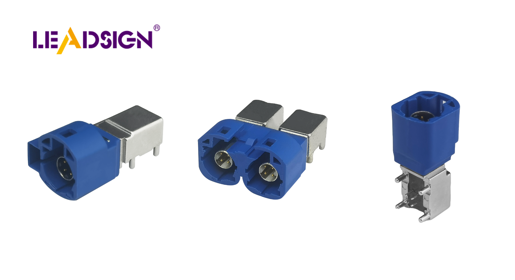
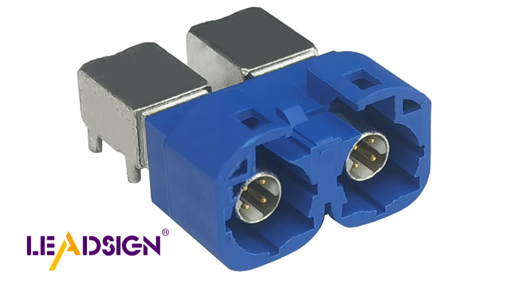
Wire-to-board connectors: These parts link wires to the PCB easily. They are made for simple use and good performance.
Wires: Pick wires that match your project’s needs. The size affects how much electricity they can carry.
Heat shrink tubing or electrical tape: These protect your connections from damage. Heat shrink tubing looks neat and professional.
Fun Fact: Wire-to-board connectors lower electronic noise, improving device performance. They also save space in small gadgets.
Having these tools and materials ready helps you succeed. Being prepared makes sure your connections are strong, efficient, and long-lasting.
Preparation
Getting the Wires Ready
Getting wires ready ensures they connect well and last long. Follow these steps to prepare them:
Cut wires to size: Use a ruler or tape to measure wire length. Cut carefully so there’s no extra or missing wire.
Remove insulation: Take off about 1/4 inch of plastic from each wire end. Use a wire stripper and avoid harming the metal inside.
Tip: Hold the wire tightly while stripping for clean, even ends.
Add solder to ends (optional): Put a little solder on exposed wire tips. This step, called "tinning," helps make better connections and improves electricity flow.
Pro Tip: Add solder to your iron's tip first for smoother tinning.
Getting the Connectors Ready
Picking and checking connectors is key for strong connections. Here’s how you can prepare them:
Pick the right connector: Choose one that fits your PCB and wire size. Crimp connectors are great for cars; terminal blocks work in most cases.
Check for damage: Look at each connector closely for cracks or bent parts. Broken connectors may cause bad connections or device issues.
Clean connectors if dirty: Wipe them with a dry cloth to remove dust or dirt. Clean connectors touch the PCB better.
Fun Fact: Good-quality connectors often have locks for extra safety.
By preparing wires and connectors properly, you ensure everything works well together. Taking time now avoids problems later and makes your project successful!
Step-by-Step Guide to Connecting Wires to a PCB
Step 1: Crimping the Wires
Crimping makes the wire and terminal connection strong. Follow these steps:
Put the stripped wire into the crimp terminal
Push the bare wire end into the crimp terminal. Make sure it fits tightly, with no metal strands outside.Use a crimping tool to secure the terminal
Place the terminal in a crimping tool and squeeze firmly. The connection should feel tight, with no loose wires visible.
Tip: Pick the right crimping tool for your terminal type. This avoids damage and keeps connections solid.
Step 2: Inserting Crimped Wires into Connector Housing
After crimping, insert wires into connector housing to lock them in place.
Match the crimped terminal with connector housing slot
Hold the wire and align its terminal with the connector slot. Correct alignment helps it slide in smoothly.Push until you hear or feel a click
Gently push until you hear or feel a click sound. This shows that it’s locked securely inside.
Pro Tip: If there’s no click, check for dirt or misalignment. Clean if needed and try again.
Step 3: Attaching Connector to PCB
Now attach your connector to connect wires with your PCB board.
Line up connector with PCB header or block
Position it so it matches perfectly with PCB pins or blocks. Proper alignment prevents damage during attachment.Press or screw connector onto PCB firmly
Press down firmly or tighten screws if available for stability. A secure fit reduces risks of disconnection later on.
Fun Fact: Some connectors have locks for extra safety in shaky areas!
By following these easy steps, you’ll connect wires to PCBs reliably! Take time, check everything twice, and enjoy completing your project!
Step 4: Testing the Connection
Use a multimeter to check if the connection works well.
Testing makes sure your connection is good and avoids problems later. A multimeter is a helpful tool for this job. Follow these simple steps:
Switch the multimeter to continuity mode
Turn the multimeter dial to the setting for checking flow. This checks if electricity moves through without stopping.Touch probes to connection points
Place one probe on the wire and another on the PCB terminal. Keep them steady for an accurate result.Listen for beep or look at screen
A beep sound or zero on the screen means it’s working fine. No beep or high numbers show there might be a problem.
Tip: If no beep, check crimp or solder again. Fix loose parts before testing once more.
Check if wire stays secure
Pull gently on the wire to see if it holds tight in place. A strong connection won’t move with light pulling.
Pro Tip: Clean your multimeter probes before using them. Dirt can make readings wrong.
Using a multimeter helps you find and fix issues early. It ensures your project will work as planned!
Common Mistakes and Troubleshooting
Common Mistakes
Stripping too much or too little wire covering.
If you strip too much, the wire can get damaged. It might also cause short circuits. Stripping too little means the wire won’t connect well. Use a wire stripper to remove just enough covering.
Tip: Expose about 1/4 inch of wire for most connectors. This keeps it safe and functional.
Using the wrong tool or connector type.
The wrong crimping tool makes weak connections. The wrong connector may not fit your board or wires. Always match tools and connectors to your project needs.
Pro Tip: Check if the connector fits your wire size and PCB design before using it.
Not securing the connector properly to the PCB.
Loose connectors can damage your PCB or cause bad connections. Misalignment or not pressing firmly are common mistakes. Take time to align and secure everything tightly.
Fun Fact: Many connectors have locks that help them stay in place, especially in vibrating areas.
Troubleshooting Tips
If wires feel loose, check and re-crimp them tightly.
Loose wires often mean poor crimping was done. Look for gaps in the crimped area. Re-crimp with proper tools if needed, pressing firmly for a tight hold.
Tip: A good crimp should keep the wire secure even with light pulling.
If no electricity flows, check for broken parts.
No continuity means something is broken in the connection path. Test with a multimeter to find breaks. Look for damaged wires or bent pins on connectors, replacing faulty parts as needed.
Pro Tip: Continuity testing quickly finds problems in PCB connections without guesswork.
Make sure connectors line up correctly with PCB headers.
Misaligned connectors disrupt how they work with PCBs. Double-check their position matches perfectly with headers before securing them tightly in place.
Fun Fact: Advanced tests can check specific parts like diodes to ensure everything works together properly on your board!
Avoid these mistakes and follow these tips for better results! Careful work now saves time fixing problems later on.
Connecting wires to a PCB is easy with clear steps. Using the right tools makes the process smoother. Preparing materials well helps avoid problems later on. Crimping wires tightly ensures strong and secure connections. Testing with a multimeter shows if everything works properly. Checking insulation and alignment stops short circuits or loose wires. Mistakes, like bad soldering, can damage your device. Work carefully, review your progress, and fix any issues you find. With patience and care, you’ll create safe and lasting connections.
What are the benefits of using wire-to-board connectors?
Wire-to-board connectors securely link wires to PCBs. They keep signals steady, reducing noise and improving device performance. These connectors save space, making them great for small gadgets.
Tip: Good-quality connectors lower risks of connection problems.
Why is proper wire connection important for PCBs?
Proper connections help circuits work correctly. A good connection keeps signals clear, reduces noise, and avoids short circuits. It also makes devices last longer and work better.
Fun Fact: Bad connections can break devices or damage PCBs permanently.
How do I choose the right wire-to-board connector?
Pick a connector that fits your PCB and wire size. Think about the type (crimp or solder), how much current it needs, and where it will be used. For cars or fast data, special connectors like HSD are best.
Pro Tip: Check if the connector matches your PCB design before buying.
What tools are essential for connecting wires to a PCB?
You’ll need a wire stripper, crimping tool, multimeter, and maybe a soldering iron. These tools prepare wires, secure them well, and test if they work properly.
Tip: Keep tools clean to make them last longer.
How can I test if my wire connection is secure?
Use a multimeter in continuity mode to check your connection. Put one probe on the wire and another on the PCB terminal. A beep or zero reading means it's working fine. If not, look for problems with the wire or connector.
Pro Tip: Tug gently on wires after testing to ensure they’re tight.
What are common mistakes to avoid when connecting wires to a PCB?
Stripping too much or too little insulation.
Using incorrect tools or wrong types of connectors.
Not aligning or securing connectors properly onto PCBs.
Avoid these mistakes for strong connections that last long.
Fun Fact: Many connectors have locks to stop accidental unplugging.
Can I use soldering instead of crimping for wire connections?
Yes! Soldering works well for through-hole connections but takes more skill. Crimping is quicker and easier with housing-type connectors.
Tip: Use a clean soldering tip for better results when soldering wires.
How do wire-to-board connectors improve device performance?
These connectors cut down noise while keeping signals stable. They make assembly faster and cheaper while boosting reliability in devices overall.
Logical Insight: Well-made PCBs with good connectors run cooler and perform better!
What should I do if my connection doesn’t work?
If it fails, check for loose parts or broken pieces. Re-crimp or re-solder as needed. Use a multimeter to find breaks in the circuit path and replace bad parts quickly.
Pro Tip: Regularly inspect tools so you don’t face repeated issues later!
Are there specific connectors for high-speed data applications?
Yes! HSD (High-Speed Data) connectors handle fast data transfer rates well. They’re used in cars, USBs, and digital systems because they hold cables tightly while working efficiently.
Fun Fact: Telecom companies also use HSDs due to their reliability!
See Also
Exploring FAKRA Connectors for PCB Automotive Solutions
Improving Data Flow Using FAKRA PCB Connectors
Boosting Automotive Communication Through FAKRA Connectors