Step‑by‑Step Guide for Car Wiring Wire Installation – Professional B2B Edition (2026)

Intro: Proper Installation Prevents Electrical Failures and Ensures Safety
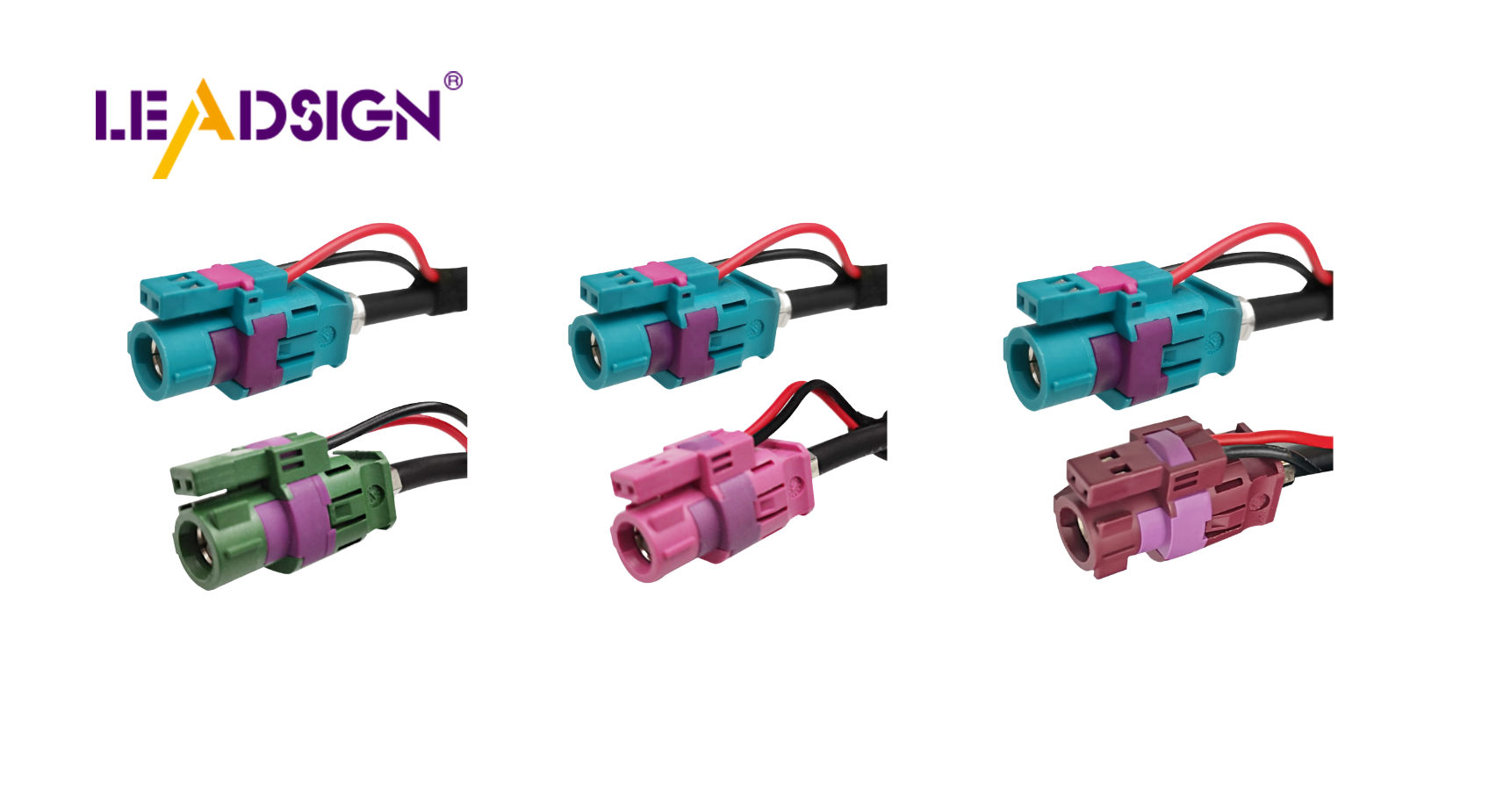
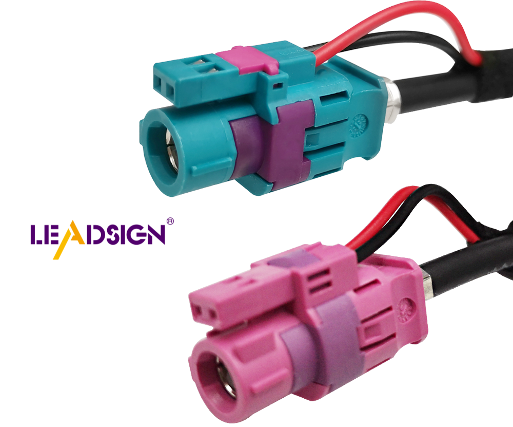
Incorrect car wiring can lead to short circuits, intermittent failures, and even electrical fires. Following a structured, step‑by‑step process – from tool selection and material preparation to routing, connecting, and testing – ensures a reliable, long‑lasting electrical system. This guide covers everything a professional technician or serious DIYer needs: essential tools, high‑quality materials, safety precautions, wiring diagram interpretation, battery connection, wire routing, component attachment, grounding, and final testing. For high‑speed data lines (cameras, GPS, USB‑C), specialised FAKRA/HSD cables are required, and LEADSIGN offers pre‑terminated solutions that eliminate field‑crimp errors.
1. Preparation – Tools, Materials, and Safety
✅ Essential Tools
Tool | Purpose |
|---|---|
Wire strippers (self‑adjusting) | Clean strip without nicking strands |
Ratcheting crimper (interchangeable dies) | Gas‑tight crimps for terminals |
Multimeter | Continuity, voltage drop, resistance testing |
Heat gun | Shrinking adhesive‑lined heat‑shrink tubing |
Soldering iron & rosin‑core solder (optional) | Low‑vibration interior splices |
Depinning tool | Removing terminals from connectors |
Cable ties / clips | Securing harness |
✅ High‑Quality Materials
Material | Why it matters |
|---|---|
Automotive primary wire (SXL, GXL, TXL) | Heat‑resistant XLPE insulation; engine bay rated |
Sealed connectors (Deutsch, Weather Pack, FAKRA) | IP67/IP68 – prevents corrosion in underbody/exterior |
Adhesive‑lined heat‑shrink tubing | Waterproof splices |
Fuse holders & relays | Circuit protection and high‑current control |
✅ Safety Precautions
Disconnect battery (negative first) – prevents shorts and sparks.
Wear safety glasses and gloves – protects against cuts, sparks, and chemicals.
Work in a well‑ventilated area – avoid soldering fumes.
Check tools for damage – frayed cords or cracked handles are hazards.
2. Understanding the Wiring Diagram
Identify power source (battery symbol) and ground points (horizontal lines).
Follow lines – trace switches, relays, and load devices (lights, motors, sensors).
Use colour coding – diagrams often match wire colours (red = +12V, black = ground).
Break down complex circuits – focus on one section at a time.
Refer to vehicle‑specific manual – avoid generic diagrams.
Pro tip: Start with a simple circuit (e.g., fog lights) to practice reading wiring diagrams before tackling full harness installation.
3. Connecting the Battery and Power Source
✅ Battery Preparation
Inspect for cracks or leaks – replace if damaged.
Clean terminals with a wire brush.
Test voltage – should be ~12.6V (full charge).
✅ Connection Steps
Place battery securely in tray.
Connect positive cable (red, “+”) – tighten with wrench.
Connect negative cable (black, “-”) – tighten.
Secure cables with zip ties – prevent chafing.
Test – turn on ignition; check for normal operation.
Safety: Never touch both terminals with a metal tool – risk of arcing.
4. Wiring Installation – Routing, Connecting, Grounding
🔹 Routing Wires
Plan shortest, safest path – avoid sharp edges, exhaust, moving parts.
Use existing channels / grommets – protect wires from abrasion.
Secure with zip ties every 15‑25 cm – not too tight.
Add protective loom (split conduit) in high‑wear areas.
Label wires with heat‑shrink markers or colour‑coded tape.
🔹 Connecting Wires to Components
Strip 5‑8 mm of insulation – do not nick strands.
Select correct terminal – match wire gauge (red=22‑18 AWG, blue=16‑14, yellow=12‑10).
Crimp with ratcheting tool; perform pull test (5‑10 lbs).
For data lines (FAKRA, HSD): use pre‑terminated LEADSIGN cables – no field crimping.
Insert terminal into housing until click; engage secondary lock.
Seal exterior splices with adhesive‑lined heat‑shrink.
🔹 Grounding and Polarity Checks
Locate ground points – chassis or engine block.
Clean surface to bare metal (remove paint, rust).
Secure ground wire with star washer – torque to spec.
Check polarity with multimeter – positive to positive, negative to ground.
Test system – lights, sensors, radio – verify function.
5. Testing and Troubleshooting the Electrical System
✅ System Check
Visual inspection – look for pinched wires, loose terminals.
Multimeter tests:
Continuity – each wire end‑to‑end (beep).
Voltage drop – <0.2V for power circuits.
Ground resistance – <0.2Ω.
Operate each device – headlights, horn, wipers, camera.
✅ Troubleshooting Common Problems
Symptom | Likely cause | Fix |
|---|---|---|
No power to device | Loose connection, blown fuse | Check fuse; re‑crimp terminal |
Intermittent operation | Loose connector, corrosion | Clean with contact cleaner; tighten lock |
Camera flickers / no image | Using power connector for video | Use FAKRA (50Ω coax) – LEADSIGN pre‑terminated |
USB‑C not recognised | Non‑HSD cable or poor termination | Use LEADSIGN HSD USB‑C cable |
6. 2026 Trends – What’s New in Car Wiring Installation
Trend | Implication |
|---|---|
4K cameras and 5G telematics | Use Mini FAKRA (20 GHz) – standard coax may lose signal over long runs. |
EV / hybrid | High‑voltage (orange) cables – do not touch. Low‑voltage data lines need double shielding. |
Pre‑terminated data cables | Shops prefer LEADSIGN plug‑and‑play FAKRA/HSD cables – no field termination errors. |
Modular wiring kits | Colour‑coded, labelled wires reduce installation time. |
7. Why LEADSIGN – Simplify Data Cable Installation
For power and ground circuits, traditional crimp or solder methods work. For high‑speed data – GPS, backup camera, 5G telematics, USB‑C, Ethernet – LEADSIGN provides pre‑terminated, colour‑coded FAKRA and HSD cables that eliminate field termination errors.
What LEADSIGN offers:
✅ FAKRA (standard & Mini) – all 14 colours, 50Ω, up to 20 GHz, IP67 optional
✅ HSD (USB‑C, Ethernet, LVDS) – 100Ω, locking, up to 5 Gbps
✅ Pre‑terminated cables – any length 0.3m – 20m, no field crimping
✅ Low‑loss, double‑shielded coax – for long runs and EV environments
✅ Bulk pricing – for shops, fleets, and distributors
For your business: When installing a backup camera or GPS antenna, use LEADSIGN pre‑terminated FAKRA cables – plug‑and‑play, perfect signal integrity, no callbacks.
Final Recommendations – Installation Checklist
Step | Action |
|---|---|
1 | Disconnect battery (negative first). |
2 | Prepare tools and materials. |
3 | Study wiring diagram – understand circuit. |
4 | Route wires away from heat/sharp edges; use grommets. |
5 | Crimp power/ground terminals; pull test. |
6 | For data lines, use LEADSIGN pre‑terminated FAKRA/HSD cables. |
7 | Secure harness with zip ties (not too tight). |
8 | Clean and tighten ground points. |
9 | Test continuity, voltage drop, and device function. |
10 | Reconnect battery (positive first, then negative). |
Remember: A well‑planned, carefully executed wiring installation prevents electrical gremlins and ensures years of reliable service.
Ready to simplify your data cable installation with pre‑terminated solutions?
[Request a free LEADSIGN FAKRA/HSD sample kit] | [Get bulk pricing]
See Also
Understanding Fakra HSD LVDS 4 Pin Connector Wiring
An Overview of Ford Fakra Connector Types
In-Depth Insights on HSD Connectors Explained
Fundamentals of HSD Connectors for Automotive Applications
Enhancing Data Transfer in Vehicles with Advanced Connectors