Step‑by‑Step Tips for Automotive Wiring Harness Kit Setup – Professional B2B Guide (2026)

Intro: Proper Installation Prevents Electrical Fires, System Failures, and Costly Callbacks
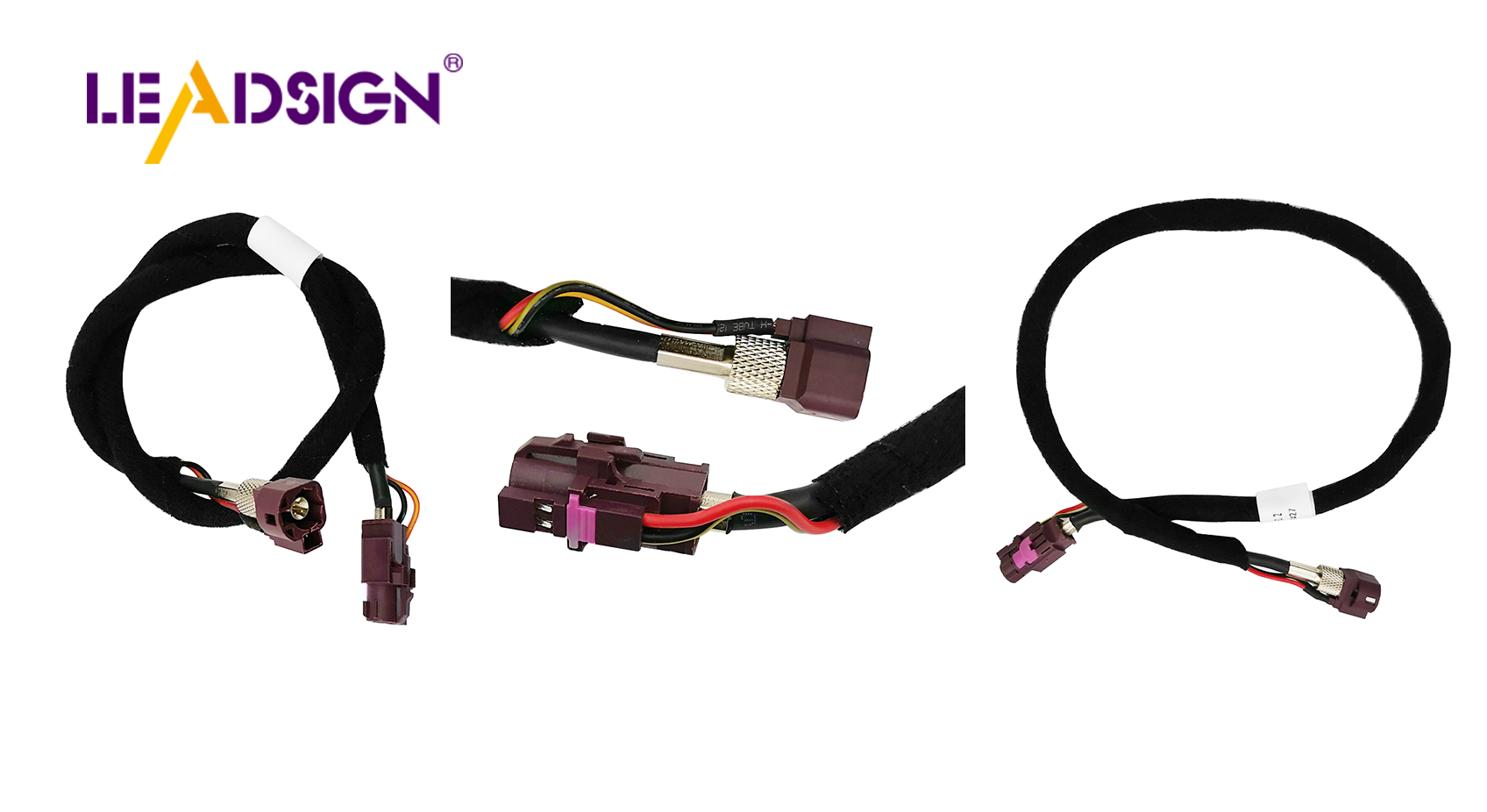
Installing an automotive wiring harness kit correctly is critical for vehicle safety, reliability, and performance. A well‑executed harness ensures that power and signals reach every component – from headlights and sensors to airbags and ECUs. Poor installation can cause intermittent failures, short circuits, or even electrical fires. This guide provides a professional, step‑by‑step process for harness setup, including tool selection, material quality, workspace safety, harness attachment, common mistakes, and final testing. For high‑speed data lines (cameras, GPS, USB‑C), LEADSIGN pre‑terminated FAKRA/HSD cables simplify installation and eliminate field‑crimp errors.
1. Tools and Preparation – What You Need
✅ Essential Tools
Tool | Purpose |
|---|---|
Wire strippers (self‑adjusting) | Remove insulation without nicking strands |
Ratcheting crimper (interchangeable dies) | Gas‑tight crimps for terminals |
Multimeter | Continuity, voltage drop, resistance testing |
Heat gun | Shrinking adhesive‑lined heat‑shrink tubing |
Soldering iron & rosin‑core solder (optional) | Low‑vibration interior splices |
Screwdrivers, pliers, pick set | General assembly, connector unlocking |
✅ High‑Quality Materials – What to Look For
Feature | Requirement | Application |
|---|---|---|
Heat resistance | 90°C (cabin), 180°C (engine bay) | Engine bay needs high‑temp wire (SXL, GXL) |
Abrasion resistance | Cross‑linked insulation | Areas near moving parts, sharp edges |
Fire resistance | UL94 V‑0 or V‑2 | Prevents flame propagation |
Flexibility | Stranded copper, TXL thin wall | Tight spaces (dashboard, doors) |
Pro tip: For high‑speed data lines (camera, GPS, USB‑C), use LEADSIGN pre‑terminated FAKRA/HSD cables – they are ready to install, no field crimping.
2. Understanding Wire Harness Components and Wiring Diagrams
🔹 Main Harness Parts
Component | Function |
|---|---|
Connectors | Link wires to devices (lights, ECUs, sensors) |
Fuses | Protect circuits from overload |
Fuse blocks | Centralise multiple fuses |
Relays | Control high‑current circuits (fans, horns) |
🔹 Reading Wiring Diagrams
Lines = wires (colours indicated)
Circles = connectors (often with pin numbers)
Splices = connections where multiple wires join
Ground symbols = chassis connection points
Practice: Trace a simple circuit (e.g., headlight) from battery → fuse → switch → relay → lamp → ground.
🔹 Labelling Wires – Easy Methods
Method | Best for | How to apply |
|---|---|---|
Heat‑shrink labels | Permanent, underhood | Write on tubing, heat to shrink |
Self‑laminating labels | Interior, serviceable | Wrap around wire, press firmly |
Cable flags | Temporary, prototyping | Clip onto wire, easy to remove |
Pro tip: Label both ends of each wire with the same code (e.g., “LH HEAD”, “GROUND”). Keep a diagram for future reference.
3. Step‑by‑Step Harness Installation
Step 1: Inspect and Prepare the Harness
Unpack the harness and lay it flat on a clean surface.
Check for damaged wires, loose terminals, or missing connectors.
Verify that the harness matches your vehicle’s wiring diagram.
Step 2: Route Wires Safely
Keep wires away from – hot exhaust, sharp edges, moving parts (steering column, pedals).
Use grommets where wires pass through metal panels.
Secure with cable ties every 15‑25 cm – not too tight.
Separate power and data lines – maintain 20 cm distance to avoid EMI.
Step 3: Join Wires – Crimping vs. Soldering
Method | Speed | Vibration resistance | Skill | Best for |
|---|---|---|---|---|
Crimping | Fast | Excellent | Moderate | Most automotive power, ground |
Soldering | Slow | Poor (brittle) | High | Low‑vibration interior signal |
Recommendation: For underhood and chassis, crimp with a ratcheting tool. For interior low‑vibration, solder is acceptable.
Crimp procedure:
Strip wire 5‑8 mm – no nicked strands.
Insert wire into terminal (match colour: red=22‑18 AWG, blue=16‑14, yellow=12‑10).
Crimp with ratcheting crimper until it releases.
Pull test (5‑10 lbs) – wire must not move.
Step 4: Protect Wires with Tubing and Grommets
Heat‑shrink tubing (adhesive‑lined) – for exterior or underbody splices.
Split loom or convoluted tubing – for abrasion protection on long runs.
Grommets – where wires pass through sheet metal.
Step 5: Secure and Ground the Harness
Use cable ties and clips – do not overtighten (allow slight movement).
Ground connections – clean to bare metal, use star washer, torque to spec. Test ground resistance (<0.2Ω).
Step 6: Test Before Final Assembly
Reconnect battery (negative last).
Use multimeter for:
Continuity – each wire end‑to‑end.
Voltage drop – power circuits <0.2V.
Operate each circuit (lights, horn, radio, camera) – confirm function.
4. Common Mistakes and How to Avoid
Mistake | Consequence | Prevention |
|---|---|---|
Over‑tightening cable ties | Crushed insulation, short circuit | Snug but not tight; allow slight movement |
Skipping connector cleaning | High resistance, intermittent signal | Clean with contact cleaner before mating |
Using substandard materials | Melted wires, connector failure | Use automotive‑grade (SXL/GXL wire, sealed connectors) |
No strain relief at connector | Wire pulls out under vibration | Zip‑tie within 5 cm of connector back |
Field‑crimping FAKRA/HSD | Impedance mismatch → no signal | Use LEADSIGN pre‑terminated cables |
5. Safety Tips – Protecting Yourself and the Vehicle
Safety rule | Why |
|---|---|
Disconnect battery (negative first) | Prevents short circuits, airbag deployment |
Wear gloves and safety glasses | Protect against sparks, sharp wires |
Work in a dry, well‑lit area | Reduces risk of shock and errors |
Keep fire extinguisher (Class C) nearby | For electrical fires |
No metal jewellery | Avoid accidental shorts |
Battery disconnect procedure:
Turn off ignition.
Remove negative cable first.
If working near airbag modules, wait 10 minutes for capacitors to discharge.
Reconnect positive first, then negative.
6. 2026 Trends – What’s New in Harness Installation
Trend | Implication |
|---|---|
4K cameras and 5G telematics | Requires Mini FAKRA (20 GHz) – use LEADSIGN pre‑terminated cables. |
EV / hybrid | High‑voltage (orange) harnesses – do not touch. Low‑voltage data lines need double shielding. |
Pre‑terminated data cables | Shops prefer LEADSIGN plug‑and‑play FAKRA/HSD – no field termination errors. |
Modular harness design | Colour‑coded wires, labelled connectors, quick‑disconnect sections. |
7. Why LEADSIGN – Simplify Data Cable Installation
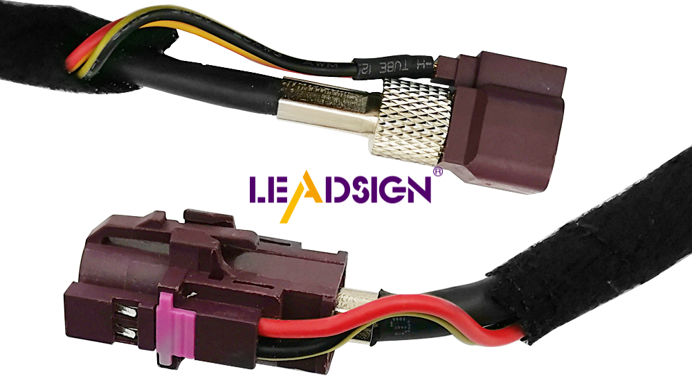
For power circuits, you can measure, cut, and crimp. But for high‑speed data (cameras, GPS, USB‑C, Ethernet), field termination is error‑prone. LEADSIGN provides pre‑terminated, colour‑coded FAKRA and HSD cables.
What LEADSIGN offers:
✅ FAKRA (standard & Mini) – all 14 colours, 50Ω, up to 20 GHz, IP67 optional
✅ HSD (USB‑C, Ethernet, LVDS) – 100Ω, locking, up to 5 Gbps
✅ Pre‑terminated cables – any length 0.3m – 20m, no crimping
✅ Low‑loss, double‑shielded coax – for long runs and EV environments
✅ Bulk pricing – for shops, fleets, and distributors
For your business: When installing a camera or GPS antenna, use a LEADSIGN pre‑terminated FAKRA cable – plug‑and‑play, perfect signal, no callback.
Final Recommendations – Harness Installation Checklist
Step | Action |
|---|---|
1 | Disconnect battery (negative first). |
2 | Prepare tools and materials (crimper, stripper, heat gun, multimeter). |
3 | Inspect harness for damage. |
4 | Route wires away from heat/sharp edges; use grommets. |
5 | Crimp power and ground terminals; pull test. |
6 | For data lines (camera, GPS, USB), use LEADSIGN pre‑terminated cables. |
7 | Secure harness with cable ties (not too tight). |
8 | Clean and tighten ground points. |
9 | Test continuity, voltage drop, and function. |
10 | Reinstall panels and final test. |
Remember: A properly installed wiring harness prevents electrical gremlins, ensures safety features work, and saves you from costly diagnostics later.
Ready to simplify your data cable installation with pre‑terminated solutions?
[Request a free LEADSIGN FAKRA/HSD sample kit] | [Get bulk pricing]
See Also
Understanding HSD Connectors Essential for Automotive Applications
An In-Depth Overview of HSD Connectors Explained
Improving Vehicle Communication Using FAKRA PCB Connectors
A Complete Overview of Ford's Fakra Connectors
Boosting Data Transmission in Vehicles with FAKRA Connectors